Free 186 More Best Homemade Tools eBook:  
New: 300+ fresh build posts/day from 275 forums → BuildThreads.com

User Tag List

Results 1 to 5 of 5

Thread: Band Saw Out Feed Table

Threaded View

  1. #1
    Supporting Member Karl_H's Avatar
    Join Date
    Sep 2013
    Posts
    1,247
    Thanks
    863
    Thanked 797 Times in 461 Posts

    Karl_H's Tools

    Band Saw Out Feed Table

    I have thought about building an out feed table for my 4x6 band saw. A few days ago I was cutting a chunk of steel and I did not catch it in time. The piece fell to the ground, catching the chip tray on the way, and I let loose a couple of swear words. The whole thing startled my wife, who came in expecting to see blood all over the place.

    Time to build an out feed table.

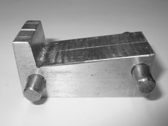
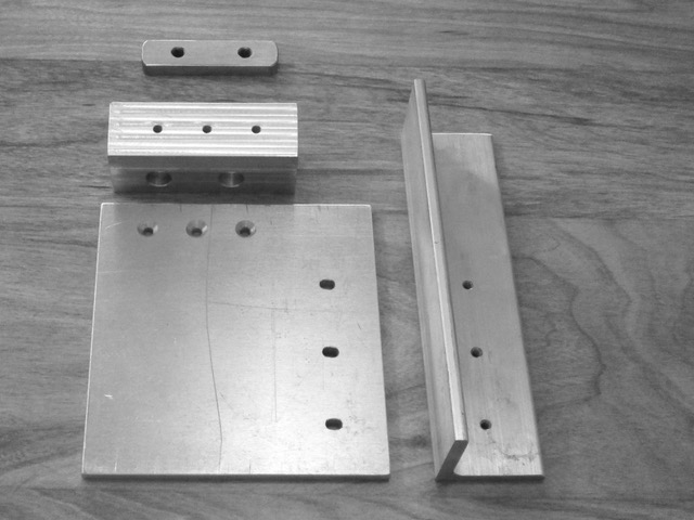
    I found a piece of 1.5 x 1.25 aluminum bar about 4.5 inches long, a piece of 5.5 x 6 x ¼ aluminum plate and a piece of 2 x 2 x ¼ aluminum angle.

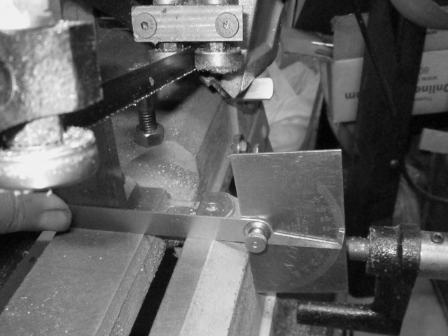
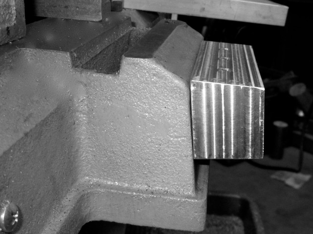
    My saw has a small ground area on the out feed side of the blade. The first thing I did was to measure the angle between the ground surface and the unground casting.

    Click image for larger version. 

Name:	01 measure angle.jpeg 
Views:	536 
Size:	75.6 KB 
ID:	34907

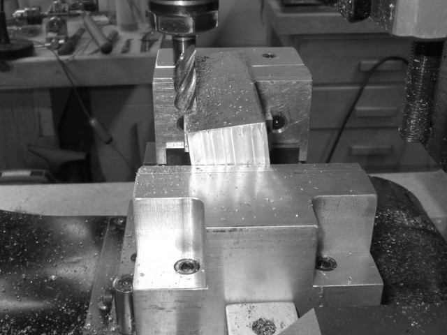
    Then I made a pair of angle bars to that angle, and cut the top surface of the 1.5 x 1.25 bar to match that angle. (See link below.)

    Click image for larger version. 

Name:	02 specially made angle blocks.jpeg 
Views:	432 
Size:	53.3 KB 
ID:	34908

    Click image for larger version. 

Name:	03 Block in place.jpeg 
Views:	406 
Size:	67.4 KB 
ID:	34909

    Click image for larger version. 

Name:	04 Ready to base block.jpeg 
Views:	423 
Size:	59.5 KB 
ID:	34910

    Click image for larger version. 

Name:	05 Cutting base.jpeg 
Views:	428 
Size:	76.6 KB 
ID:	34911

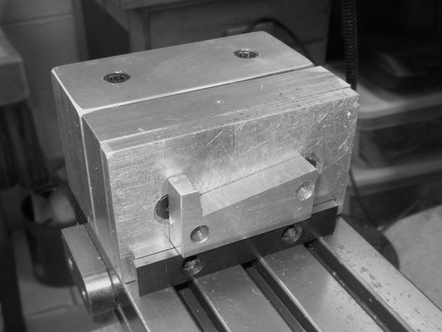
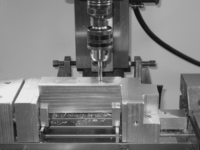
    I used the angle bars again when I drilled and tapped the holes for the table.

    Click image for larger version. 

Name:	06 Tapping base.jpeg 
Views:	420 
Size:	69.2 KB 
ID:	34912

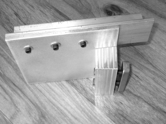
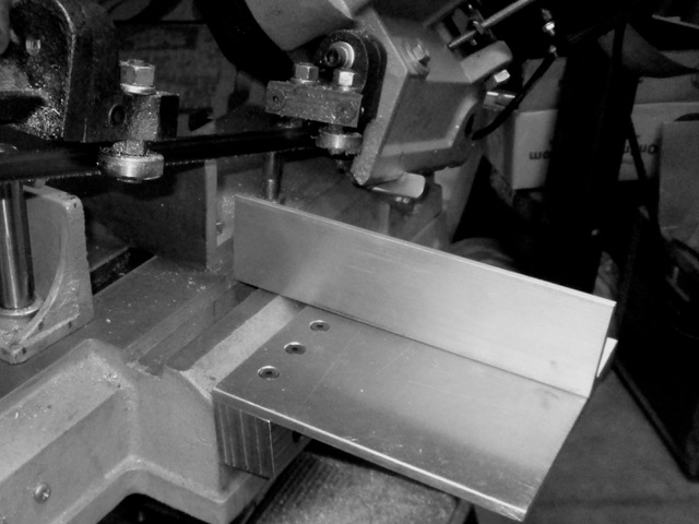
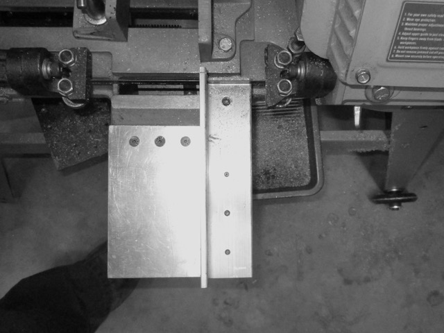
    I used small slots to mount the angle iron (aluminum) to the new table so I could make any adjustments to align it with the fixed vise jaw.

    Click image for larger version. 

Name:	07 Parts ready to assemble.jpeg 
Views:	433 
Size:	69.5 KB 
ID:	34913

    Click image for larger version. 

Name:	08 Parts assembled.jpeg 
Views:	380 
Size:	75.1 KB 
ID:	34914

    To align everything up, I clamped a bar in the saw vice, then clamped the out feed table to the bar.

    Click image for larger version. 

Name:	09 Aligning parts.jpeg 
Views:	415 
Size:	72.9 KB 
ID:	34915

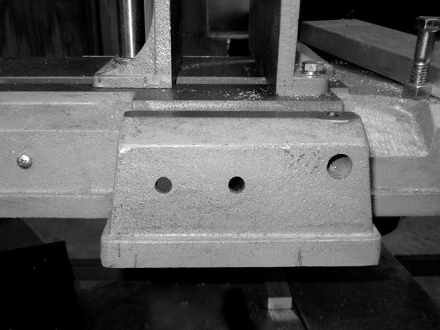
    Once I was satisfied everything was in alignment, I used a transfer punch to carry the holes from my new base to the cast iron of the saw.

    Click image for larger version. 

Name:	10 Two holes drilled in saw.jpeg 
Views:	402 
Size:	80.5 KB 
ID:	34916

    Click image for larger version. 

Name:	11 Base in place.jpeg 
Views:	413 
Size:	78.5 KB 
ID:	34917

    Click image for larger version. 

Name:	12 Everyting assembled.jpeg 
Views:	419 
Size:	67.8 KB 
ID:	34918

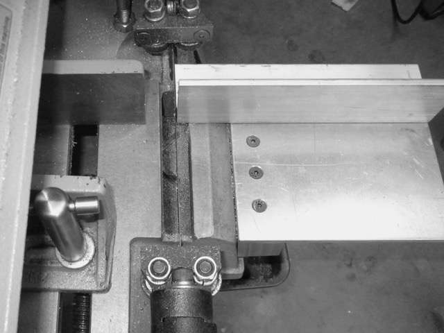
    One thing I did not anticipate was to provide access to the set screw for the built in cut off gauge. I rarely use it, but I thought I should still drill an access hole. This is visible on the next picture.

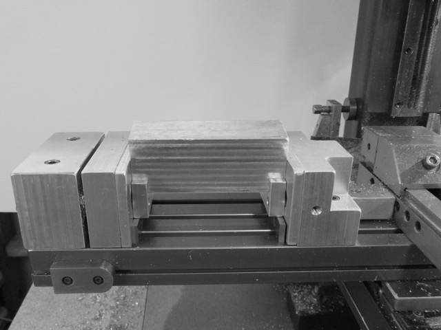
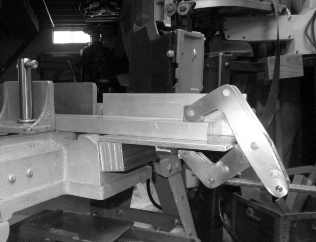
    The new out feed table precludes me using the factory stop block for anything less than 7 inches from the blade, but it will work if I need it for longer pieces. I am considering a stop block to fit on the fixed jaw extension, but most of my work is one off pieces, so I haven’t done that yet.

    With everything mounted and aligned, the final step was to cut the aluminum angle to length. This close fit seems fine now, but it may become an issue when I install a new blade or if the current blade gets knocked out of alignment. It would be an easy task to file it back a bit.

    Click image for larger version. 

Name:	13 Fence cut to length.jpeg 
Views:	450 
Size:	66.8 KB 
ID:	34919

    Click image for larger version. 

Name:	14 Finished.jpeg 
Views:	442 
Size:	72.0 KB 
ID:	34920

    I hope this inspires some one.

    Comments and questions are welcome.

    Details about making the specialized angle blocks can be found here:
    Specialized Angle Blocks

  2. The Following 13 Users Say Thank You to Karl_H For This Useful Post:

    arvidj (May 12, 2020), emu roo (Sep 24, 2025), fizzloid (Dec 10, 2022), high-side (May 17, 2020), JoeH (May 12, 2020), Jon (May 14, 2020), katy (May 12, 2020), lassab999 (Sep 21, 2023), Rangi (May 11, 2020), terence b (Sep 24, 2025), Tonyg (May 11, 2020), Toolmaker51 (May 11, 2020), Z2V (May 12, 2020)

Thread Information

Users Browsing this Thread

There are currently 1 users browsing this thread. (0 members and 1 guests)

Bookmarks

Posting Permissions

  • You may not post new threads
  • You may not post replies
  • You may not post attachments
  • You may not edit your posts
  •