
 LinkBack URL
 About LinkBacks


This thread details making heading elements from the wire roll to the
element ready to install. The tools made and the procedure used to
make them. Errors, mistakes and solutions are included.
I got the technical design information needed in the 2 references below.
The third is information in regard to Kanthal, a trade name for
iron-chromium-aluminium alloys. They explain it much better that I can.
1) The most entry level explanation, with tables for nichrome wire.
https://wiretron.com/wp-content/uplo...CrTechTips.pdf
2) Much deeper engineering level information, manufacturer supported web site.
https://www.kanthal.com/en/knowledge...-calculations/
3) Just some facts about.
https://facts.net/science/chemistry/...about-kanthal/
From my limited experience, the most critical design consideration is
the POWER DENSITY or SURFACE LOAD which is watts ÷ surface area
of your element. DO NOT, push this limit.
My first attempt at making elements for my crucible furnace ended in failure.
I had read a little about design requirements but pressed those limits outside
that envelope. The elements burned out after about 2 hours of testing.
After studying more, I cut the power cut over 50%, and switched from
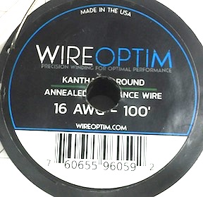
Nichrome wire to Kanthal which allowed larger gauge wire
Kanthal has higher resistance, is a lot stiffer than Nichrome and
longer lasting. It is also a little more costly.
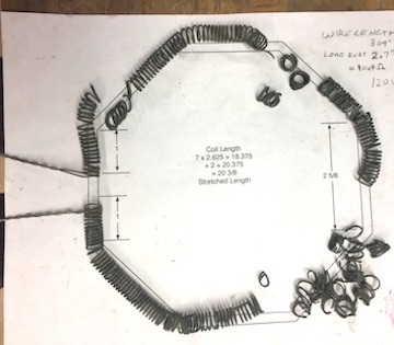
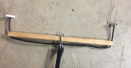
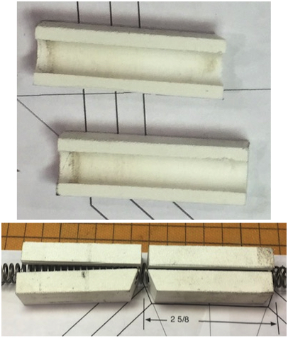
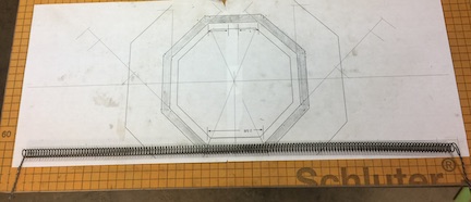
I am using fire brick recovered from an old kiln, the grooves are about 0.405 wide
and 0.500 deep. I have room for about 82 of element. The furnace is small, with
a 5 1/2 octagon chamber. There are 4 grooves, so 4 - 20 elements rather than
one continuous. Elements will be connected in series outside the heat chamber.
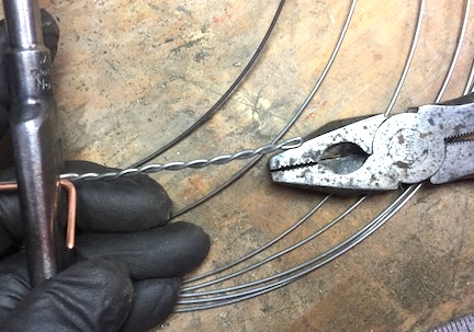
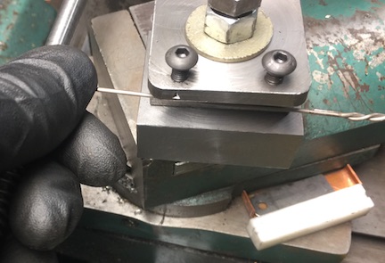
The ends of the elements need to be doubled over and twisted together. It seems most
wind the coil first then twist the ends. It is easier, for me, to be accurate by twisting the
ends first. A tap wrench with a copper wire to take up space and pliers worked well for twisting.
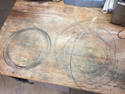
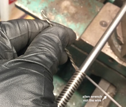
The wire came off the roll very springy with some inconsistent random bends.
The Kanthal wire has very strong memory and wants to remain coiled
When I tried to wind the first coil the memory in the wire made the coils inconsistent.
KanthalA is a lot more stiff than the Nichrome 80, My new elements are also
thicker (0.0510) than the old (0.0403).
The wire needed to be straightened. I sometimes hold one end of a wire in the vise and
PULL the other end with pliers. Kanthal is too tough to straighten this way. Also, my shop
is not large enough to get that far from my vise.
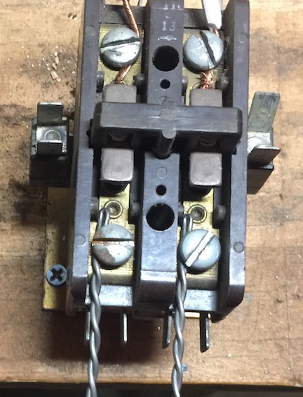
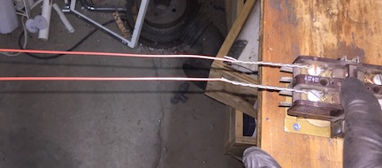
I decided to try heat to straighten the wire. I screwed an old 2 pole electrical contactor
to my bench top. I use this rather than a switch because it is more robust, can be securely
attached to the bench, and the elements lead straight away.
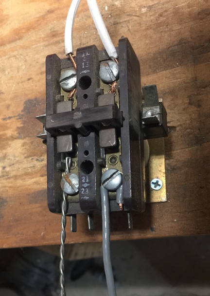
I had to straighten one element a second time because I messed it up.
It may actually be better to straighten one wire at a time. You have to
use a second non-resistive wire. You can use 1/2 the voltage to do one at a time.
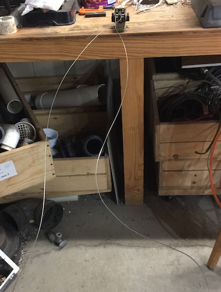
The other ends were connected to a heavy gauge wire on a wood spreader. The heavy
wire was chosen for stiffness rather than current carry capacity.
The center of the spreader is connected to a rubber tarp strap. Then strap stretched
to put tension on the wires. The center is important as it assures the same force is
exerted on both wires. If you do one wire at a time, move the strap closed to the element end.
Connect the contactor to an appropriate voltage source. I just activated the contractor
with my finger. Let the element heat to dull red. Then cool. I had to try this a couple of
times, increasing the on time and tension a little each try.
The straightened wire is much nicer to work with.
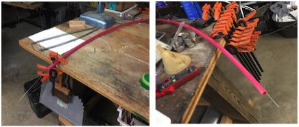
My shop gets cluttered, even if was as neat and tidy as I wish, there no good place
to put a 16 foot piece of straight wire to feed it into the machine. The smooth gentle
curve of PEX water pipe, clamped to the bench, provides a smooth path over the clutter.
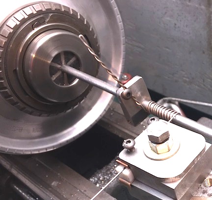
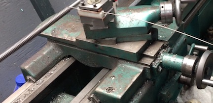
A lathe provides an ideal platform wrap the elements. A 5/16 steel rod is the mandrel.
It is held in my old style collet chuck which also provides a nice hand wheel for turning
the beginning and end of the coil by hand.
An easily adjustable anchor attaches the wire to the rod for winding. The angle is the
approximate helix angle allows the wire lead to pass the feed block on the first few turns.
Tension on the wire applies significant bending force to the mandril. A follow rest provides
support for the long thin rod.
( Easy Follow Rest)
The far end of the rod is simply center drilled and supported with a live center
The wire needs to feed smoothly to the mandrel, held close and advanced to
appropriately space the coils. Keeping it under tension make the coils nice and tight.
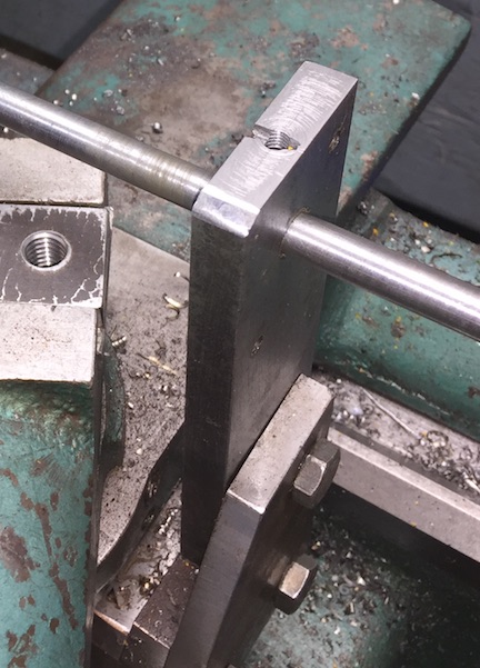
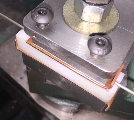
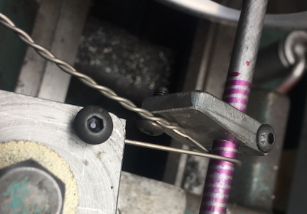
I found some steel chunks that bolt to the top slide of the lathe. I trimmed these to
appropriate size and drilled them for a bolt, and two machine screws.
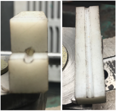
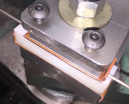
To prevent the wire from scraping across the steel, HDPE guide blocks provide
a smooth path. In order to get 1/2 a groove on the edge of a block I clamped
2 small pieces together, and drilled a small hole between them. One block is used
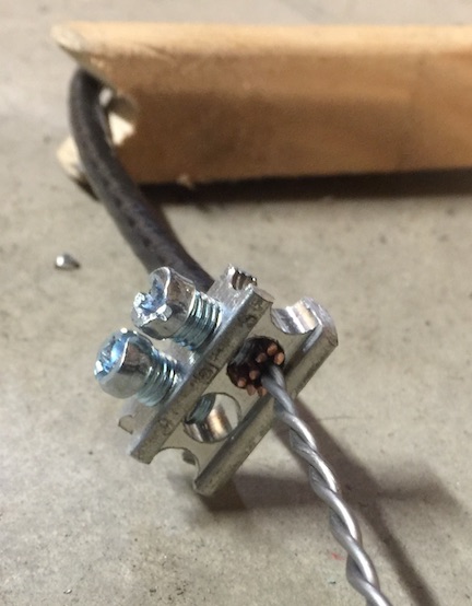
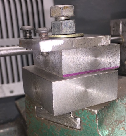
with a copper friction plate to apply tension to the wire.
The friction parts are held in place in similar fashion to a bench hook.
Tension is adjusted with 2 screws in the top plate. The tension screws
press on a steel plate (old hacksaw blade) rather then the copper.
The copper is recovered from old plumbing pipes.
(Welding Chill Plates)
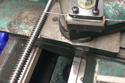
Run spindle in reverse, with the wire feeding over the top and advancing toward the
tailstock. This allows you to watch the wire feed onto the mandrel, rather than after
it has made a full turn.
The designed wire spacing is 0.1205. Fastest feed rate is 0.05000 without swapping gears.
The gear swap only gets to 0.1000". Half-nut feed rate is 2.5 times the feed clutch
I used the 9 TPI setting to get 0.1111 per revolution. The element will be stretched
a little after winding to achieve proper length.
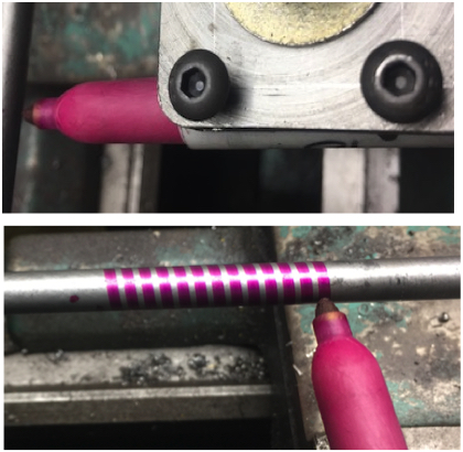
I put a sharpie in place of the guide block to test the set up and to mark the wire path
on the mandrel. (I would like to claim that I planned for the pen to fit, but that was just luck.)
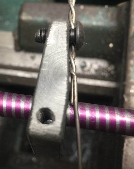
Attach the twisted wire end to the anchor. Clamp securely, the first couple of
turns place a lot of stress on the anchor. My first 2 attempts, the anchor slipped
on the mandrel. Then the wire tried to escape the holding screw. If I had more
elements to make, I would cut a groove in the anchor for the wire.
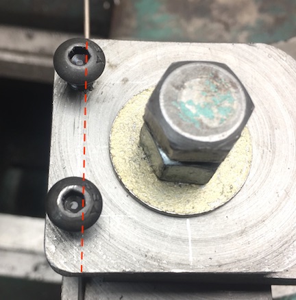
With the top slide set at about 30˚ you can use the it and the cross slide in
combination to align the wire with the center of the guide block holder.
Install the guide block and tension plate, make sure the wire is in the groove,
and apply a little tension. When making my nichrome coils I used too much tension
and broke the wire. But those were oak blocks and nichrome is not as strong as Kanthal.
The HDPE and the Copper are consumable items.
Turn the spindle by hand while watching to be sure the anchor and wire will
miss the guide assembly.
When you are confident everything is correct, start the machine.
As the twisted end nears the guide blocks, stop the machine. Turn the spindle
by hand to get the twist close to the guide.
Firmly GRIP the wire, remove the guide and move the carriage away.
Finish wrapping the last couple turns by hand.
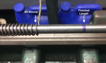
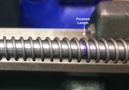
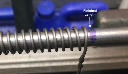
SLOWLY let the spring unwind. Mine backed up a bit more than 7 turns.
If you have room, you can stretch the coil to final length while still on the mandrel
Pull the end past the finished length
Repeat until it is close. Better a little short than too long.
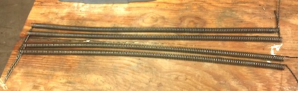
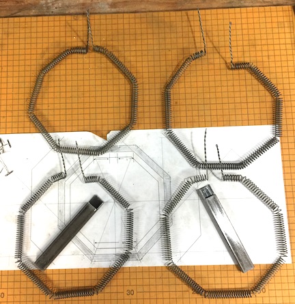
4 wound elements
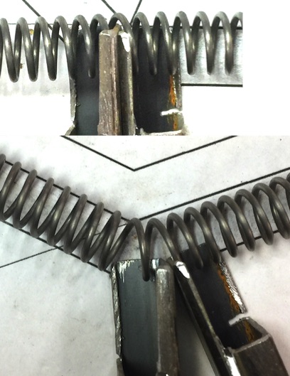
The next step is to bend the elements to fit into the grooves. I tried this different ways.
First was sliding rods into the coils. That worked OK for the first bend, but does not work
for subsequent bends.
I tried blocks with a slot to try to grip the outside of the coil. They were awkward to use
and spread the bend out over several turns.
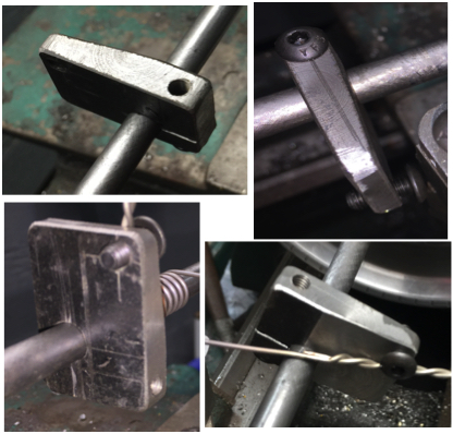
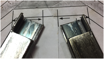
The final solution was make levers from some small rectangular steel tubing.
This worked well. Notice there is a right and left.
Center the element over a paper pattern.
Insert the levers between two coils. Open the levers holding the tips together and the
wire against the tips. I found it best to spread the bend over 2 turns.
The top coils are the first using the various methods. The bottom two were made with the levers.
Off to put them in the furnace. Will update soon.


 Reply With Quote

Bookmarks