
 LinkBack URL
 About LinkBacks


This an update to the crucible furnace project I posted earlier.
Electric Crucible Furnace
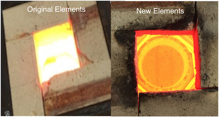
The original elements burned up. The design was corrected and
new elements were made. This is how the elements were made.
Crucible furnace heating elements
Design of the new elements is well with-in the recommended design
parameters. They draw much less current and a simplified wiring configuration
allows the control box to be easily moved safely away from the hot activity around the furnace.
If you have worked with hot metal very much, can tell buy the temperature color
that the original elements were way too hot.
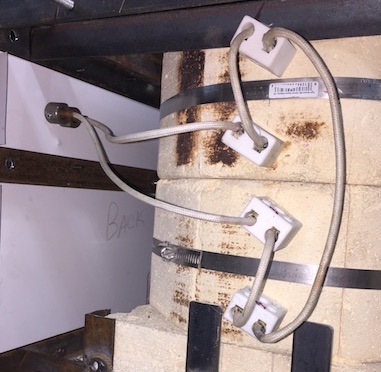
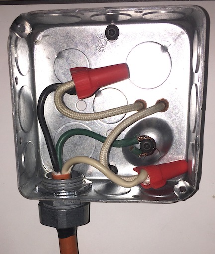
The 4 elements are connected outside the chamber using ceramic junction
blocks. High temperature wire and the twisted element ends overlap inside
the connectors so that both screws tighten on both the wire and the element.
This assures a low resistance connection.
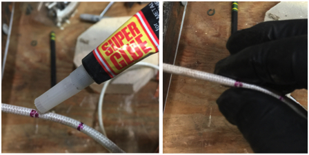
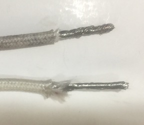
The high temperature wire, insulated with fiberglass and mica, frays VERY
easily when stripped. After a few messy attempts, I massaged couple of
drops of super glue into the outer layer before stripping it. RUBBER GLOVES
are essential. This made a much neater termination.
While the frayed does not look terrible. The glue makes it much easier to strip the ends.
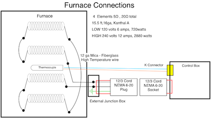
The High Temp wires lead to a simple junction box mounted outside the furnace
where they connect to a 12/3 cable and terminate in a plug the will connect to
the control box. This is a good location to use a clamp-on amp meter if desired
to verify current level.
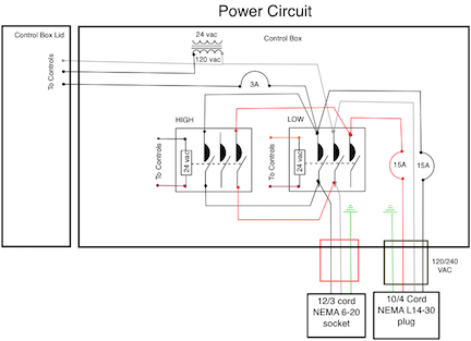
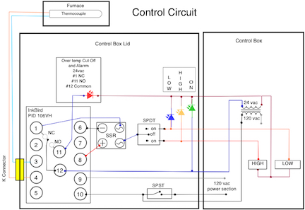
For clarity the wiring diagrams are divided into POWER and CONTROL.
It worked out well to put the power components in the box and the
low current control components in the lid.
(NOTE; Since this is an international forum, it may be important to mention I am in
the US. Residential power to homes is 120v/240v, 3 wires, with 2 hot wires and
a neutral. Either HOT to Neutral is 120. While Hot to Hot is 240v)
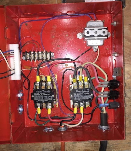
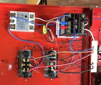
The power section has two 3-pole contactors to provide low and high settings(720 vs 2880 watts).
The power cord is much larger gauge than required. The original design was almost
6000 watts, this design is less than 3000. I did not change the power cord. Power
enters through 15 amp circuit breakers, then terminate on the LOW contractor.
Additional terminals on the contractor allow connections to supply a 24vac transformer
and the PID controller through a 3 amp breaker and a switch. Jumper wires connect
the input sides of the LOW and HIGH contactors. The output side of HIGH also connects to
the output side on the LOW contactor. On LOW, Hot #1 and Neutral (120v) power the furnace.
On HIGH, H1 and H2 (240v) power the furnace.
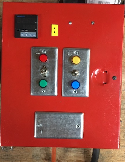
The control section is mounted on the box lid. Conductors pass through a plastic block
to prevent damage as the lid opens and closes. An InkBird PID 106VH Controller monitors
the temperature, cycling the elements through a Solid State Relay.
(This PID106 is available in a 24v version as well as with relay output rather
than SSR. If I had been aware, wiring would have been a little simpler)
One switch energizes the controller and a 24VAC transformer for the contactors.
The second switch selects HIGH, OFF, or LOW. The controller has an alarm function,
which is configured to cut power to the contactors in the event the Solid State Relay fails.
Thanks to Dr AL for the heads up that SSRs tend to fail on the ON position.
Heat Treatment Oven (with separate control cabinet)
Thanks to all that have provided ideas and inspiration.


 Reply With Quote

Bookmarks