Free 186 More Best Homemade Tools eBook:  
Get 2,000+ tool plans, full site access, and more.

User Tag List

Page 2 of 5 FirstFirst 1 2 3 4 5 LastLast
Results 11 to 20 of 44

Thread: Cylindrical square from a lathe tailstock.

  1. #11
    Supporting Member DIYSwede's Avatar
    Join Date
    May 2019
    Location
    Stockholm, Sweden...
    Posts
    634
    Thanks
    415
    Thanked 799 Times in 319 Posts

    DIYSwede's Tools
    Not only being cheap and lazy, I figured out the fastest way to obtain a suitable piece
    will be to visit my closest merchant shipping yard, where the guys overhauling marine diesels dwell.

    One or a few discarded biggie wrist/ gudgeon pins could perhaps be around for a smallish fee?
    Case hardened with nice wall thickness and weight, the ends should be pretty easy to grind and lap.
    Their perimeter being hardened, ground and polished for starters, I guess the conrod/ piston sees the most wear?

    Or is this just wishful thinking, again?

    Cheers

    Johan

    186 More Best Homemade Tools eBook

  2. #12
    Supporting Member tonyfoale's Avatar
    Join Date
    Nov 2016
    Location
    Spain
    Posts
    1,557
    Thanks
    686
    Thanked 2,643 Times in 708 Posts

    tonyfoale's Tools
    Quote Originally Posted by DIYSwede View Post
    Not only being cheap and lazy, I figured out the fastest way to obtain a suitable piece
    will be to visit my closest merchant shipping yard, where the guys overhauling marine diesels dwell.

    One or a few discarded biggie wrist/ gudgeon pins could perhaps be around for a smallish fee?
    Case hardened with nice wall thickness and weight, the ends should be pretty easy to grind and lap.
    Their perimeter being hardened, ground and polished for starters, I guess the conrod/ piston sees the most wear?

    Or is this just wishful thinking, again?

    Cheers

    Johan
    Well worth a try. Also prompts the thought that maybe truck engines have suitable donor pins for a small square, you do not always need a large one. In fact I think that I have one laying around somewhere, I'll have to look it out and see what I can do. Thanks for the idea.

    2000 Tool Plans

  3. #13
    Supporting Member DIYSwede's Avatar
    Join Date
    May 2019
    Location
    Stockholm, Sweden...
    Posts
    634
    Thanks
    415
    Thanked 799 Times in 319 Posts

    DIYSwede's Tools
    Quote Originally Posted by tonyfoale View Post
    Well worth a try. Also prompts the thought that maybe truck engines have suitable donor pins for a small square, you do not always need a large one. In fact I think that I have one laying around somewhere, I'll have to look it out and see what I can do. Thanks for the idea.
    Absolutely - for instance bolted on a lathe faceplate or mill table if you're lacking a true angle plate,
    or when your's just a tad too big for the current job, or even when you're making one yourself.
    As per Howard Hall's excellent home page: Machining an Angle Plate or Cylindrical Square setups on the milling machine

    When finding a few pins at the scrap yard, they'd easily be checked for wear by just putting them together against some light source.
    Grinding/ honing the ends should be pretty straightforward, then roughly cutting them to suitable length -
    no need to overdo that, as only the business end of it really needs to be absolutely true.
    Personally I'd aim for max 6 to 8 in L/D ratio, as I don't want to push my luck too far.


    Cheers
    Johan

  4. #14
    Supporting Member tonyfoale's Avatar
    Join Date
    Nov 2016
    Location
    Spain
    Posts
    1,557
    Thanks
    686
    Thanked 2,643 Times in 708 Posts

    tonyfoale's Tools
    Quote Originally Posted by DIYSwede View Post
    When finding a few pins at the scrap yard, they'd easily be checked for wear by just putting them together against some light source.
    Grinding/ honing the ends should be pretty straightforward, then roughly cutting them to suitable length -
    no need to overdo that, as only the business end of it really needs to be absolutely true.
    Personally I'd aim for max 6 to 8 in L/D ratio, as I don't want to push my luck too far.


    Cheers
    Johan
    By sheer accident I came across this, rather tedious but..................

  5. #15
    Supporting Member Toolmaker51's Avatar
    Join Date
    Feb 2016
    Location
    Midwest USA
    Posts
    5,331
    Thanks
    7,042
    Thanked 2,980 Times in 1,893 Posts

    Toolmaker51's Tools
    Tony is right......By sheer accident I came across this, rather tedious but..................haven't seen ANY as tedious. Yikes.
    First off, the squareness interpretation is compromised by not insuring a consistent axis from the base [of cylinder square] to the indicator point. Sliding it past; all kinds of iffy-bizzyness. A simple fix would clamp stiff drill rod or equivalent along edge of indicator foot, elevated somewhat above surface plate, to create a Vee [repeating] locator.
    A flat would not function perfectly, by introducing potential secondary cant or compound tilt of cylinder being examined. The front edge should be relieved against burr or dirt as well.
    "My first video. . ." he says.
    Yup, looks to be the case.
    Last edited by Toolmaker51; Jan 4, 2020 at 12:53 PM.
    Sincerely,
    Toolmaker51
    ...we'll learn more by wandering than searching...

  6. #16
    Supporting Member Frank S's Avatar
    Join Date
    Aug 2015
    Location
    Peacock TX
    Posts
    11,210
    Thanks
    1,982
    Thanked 8,785 Times in 4,206 Posts

    Frank S's Tools
    Ok there was something I thought I noticed in the My first video that doesn't compute unless the wrist pins have a slight taper to one or the other of them.
    the one that was lapped and showed about a .ooo5 max from zero when he found the center. then with the other pin he had to re zero the gage half way round from the first. I would have thought that you would not re zero your instrument. rather the zero whole have been left alone and the cylinder rotated and moved to locate high center to show either a zero positive or a zero negative at some point on the cylinder baring any cylindrical taper from end to end the indicator should have given a reading of zero, zero there should actually be two 0-0 indications providing the base was perfectly squared and perpendicular to the axis of the indicator in the horizontal plane.
    I used to check cylindrical squareness between 2 cylinders without an indicator on a slab by positioning a true straight edge on the slab weighting it so it could not move push both cylinders against the knifed edge and bring them together with a light behind them then rotate first one then the other until there was zero light shining between them then rotate first one and then the other to find the 2nd zero light position if there happened to be one noting one each where the points of cbest contact occurred. and attempt to lap accordingly.
    Intense light can penetrate even .0000001 and if you have the light shielded so it can only be immitted through a narrow slit in a room with subdued illumination and 2 as near to perfectly ground cylinders as reasonably possible eventually you will wind up with a pair of cylindrical squares.
    There is a way to do this just like the 3 plate lap but for that you need 5 cylinders 2 of which needs to be longer than the 3 and clamped together on laying flat on the slab while you use the 3 to lap against the ends of each other while laying in the v of the 2 longer cylinders. It helps if the 2 longer cylinders have a machined relief in the center of them to allow the lapping compound a place to go that will not contaminant the cylindrical surfaces of either the cylinders having the ends lapped or the 2 cylinders being used as the straight V" surface
    Never try to tell me it can't be done
    When I have to paint I use KBS products

  7. #17
    Supporting Member tonyfoale's Avatar
    Join Date
    Nov 2016
    Location
    Spain
    Posts
    1,557
    Thanks
    686
    Thanked 2,643 Times in 708 Posts

    tonyfoale's Tools
    Quote Originally Posted by Frank S View Post
    Ok there was something I thought I noticed in the My first video that doesn't compute unless the wrist pins have a slight taper to one or the other of them.
    I linked to that video only because it showed the use of large gudgeon pins as cylindrical squares in response to Johan's posts. I could see that it was a tedious video and so I only skimmed through it at double speed with no sound on. Frank, you obviously studied it much closer than I.

  8. #18
    Supporting Member DIYSwede's Avatar
    Join Date
    May 2019
    Location
    Stockholm, Sweden...
    Posts
    634
    Thanks
    415
    Thanked 799 Times in 319 Posts

    DIYSwede's Tools
    Quote Originally Posted by Frank S View Post
    There is a way to do this just like the 3 plate lap but for that you need 5 cylinders 2 of which needs to be longer than the 3 and clamped together on laying flat on the slab while you use the 3 to lap against the ends of each other while laying in the v of the 2 longer cylinders. It helps if the 2 longer cylinders have a machined relief in the center of them to allow the lapping compound a place to go that will not contaminant the cylindrical surfaces of either the cylinders having the ends lapped or the 2 cylinders being used as the straight V" surface
    -Thanks Tony, TM51 and Frank for suggestions and corrections. I found the video more food for my thoughts than a pure how-to.
    Also - your suggested machining and measurement methods are truly appreciated.
    Frank's lapping method will probably come to use after end cutting/ grinding/ relieving.
    Now I've just gotta sit on my hands waiting for the scrap yards/ service shops to open after all these holidays...

    Cheers
    Johan

  9. #19
    Supporting Member tonyfoale's Avatar
    Join Date
    Nov 2016
    Location
    Spain
    Posts
    1,557
    Thanks
    686
    Thanked 2,643 Times in 708 Posts

    tonyfoale's Tools
    Quote Originally Posted by DIYSwede View Post
    -Thanks Tony, TM51 and Frank for suggestions and corrections. I found the video more food for my thoughts than a pure how-to.
    Johan
    That is what I intended when I posted it.

    Quote Originally Posted by DIYSwede View Post
    -Now I've just gotta sit on my hands waiting for the scrap yards/ service shops to open after all these holidays...
    Johan
    So is Sweden like Spain in which the main day is tomorrow, the 6th? Things do not get back to normal until Tuesday at the earliest.

    If you had to pay someone to grind a used gudgeon pin to true it maybe it would make more sense to go and buy a new one.

  10. #20
    Supporting Member DIYSwede's Avatar
    Join Date
    May 2019
    Location
    Stockholm, Sweden...
    Posts
    634
    Thanks
    415
    Thanked 799 Times in 319 Posts

    DIYSwede's Tools
    Quote Originally Posted by tonyfoale View Post
    So is Sweden like Spain in which the main day is tomorrow, the 6th? Things do not get back to normal until Tuesday at the earliest.

    If you had to pay someone to grind a used gudgeon pin to true it maybe it would make more sense to go and buy a new one.
    Yup - quite a few enterprises of interest closed on Dec 23rd, and opens Tuesday at the earliest.
    Personally, I'll start working next Monday, and having had my hands full of hungry, ungrateful heirs up 'til now,
    I hope to get a few days of shopwork done from Tuesday when my love takes off for a week in Hong Kong.

    Thanks for the tip, but being Über-cheap, I can easily get 20 dollars worth of odd tools and spend a day's DIY work to save 5 bucks!
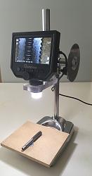
    My real rush kicks in when taking some odd, cheap or free piece totally outta its intended use for my perverted desires, as this
    iSore™ Tool Series
    Cylindrical square from a lathe tailstock.-img_e0625.jpg
    Microscope stand from an orange press, (2 buck flea market find) a PC plastic offcut and a HD disk.

    My smugness triumphs when walking in a hardware store checking all the new, branded tools "suffering from Design".
    Buying ready-mades is merely for "amateur hobbyists", not us die-hard compulsory DIY machinists!

  11. The Following User Says Thank You to DIYSwede For This Useful Post:

    Toolmaker51 (Jan 5, 2020)

Thread Information

Users Browsing this Thread

There are currently 1 users browsing this thread. (0 members and 1 guests)

Tags for this Thread

Bookmarks

Posting Permissions

  • You may not post new threads
  • You may not post replies
  • You may not post attachments
  • You may not edit your posts
  •