Free 186 More Best Homemade Tools eBook:  
Get 2,000+ tool plans, full site access, and more.

User Tag List

Page 1 of 4 1 2 3 4 LastLast
Results 1 to 10 of 44

Thread: Cylindrical square from a lathe tailstock.

Hybrid View

  1. #1
    Supporting Member tonyfoale's Avatar
    Join Date
    Nov 2016
    Location
    Spain
    Posts
    1,575
    Thanks
    696
    Thanked 2,652 Times in 712 Posts

    tonyfoale's Tools

    Lightbulb Cylindrical square from a lathe tailstock.

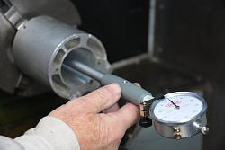
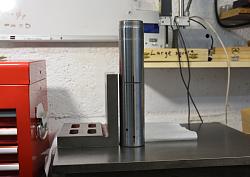
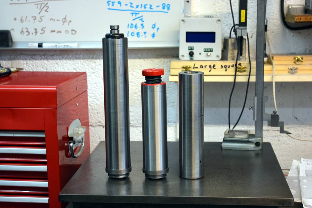
    I had a spindle from the tail stock of a large lathe which I used as the basis for an accurate cylindrical square. Although the spindle was hardened it had some wear due to years of use on the lathe. This video shows how I lapped it true and checked it for squareness.


    here is a link to my Youtube playlist of more workshop videos.

    https://www.youtube.com/playlist?lis...O1hdmUIYO28Def

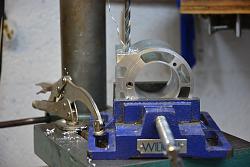
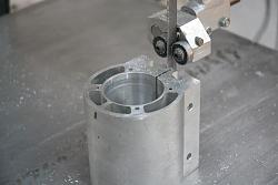
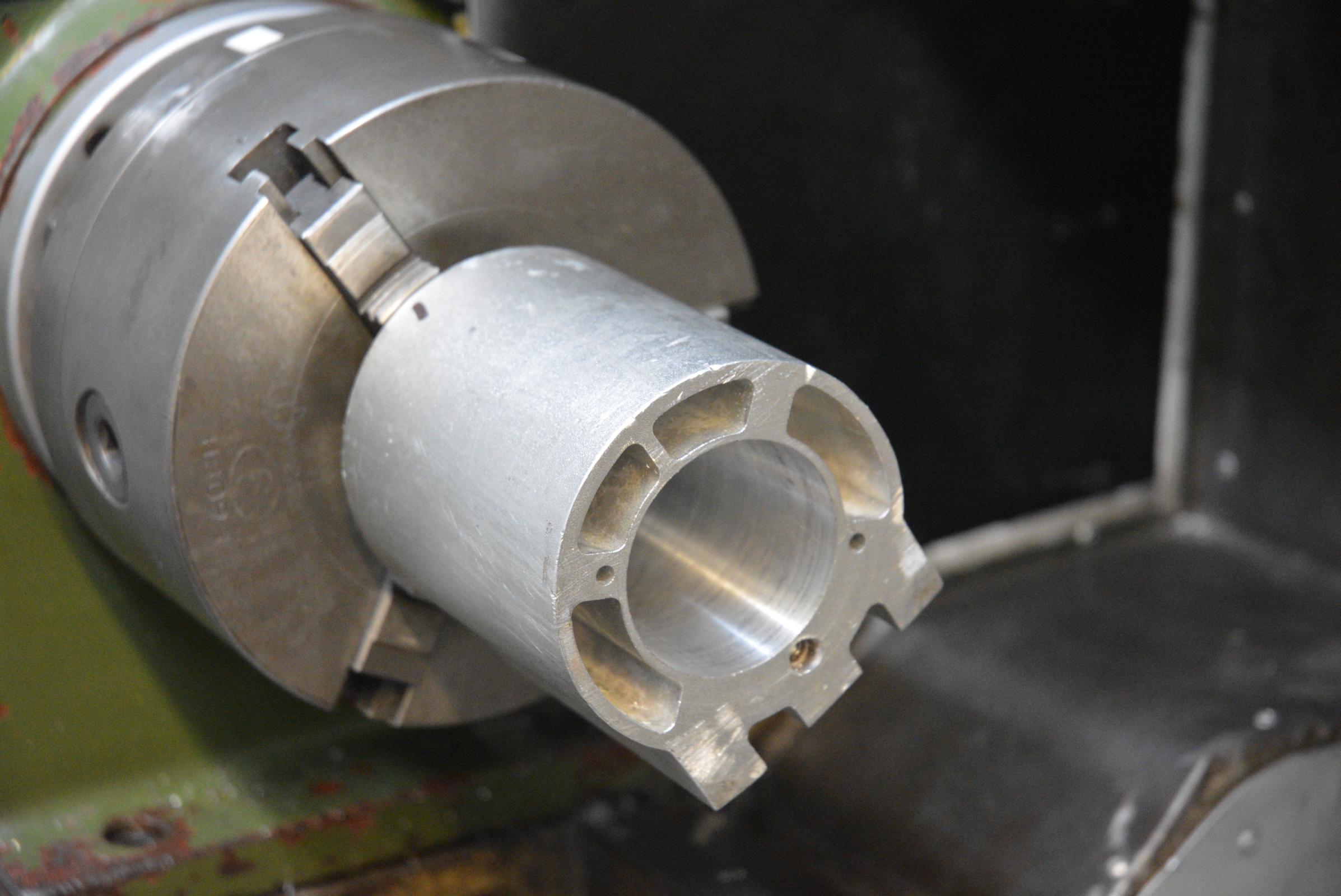
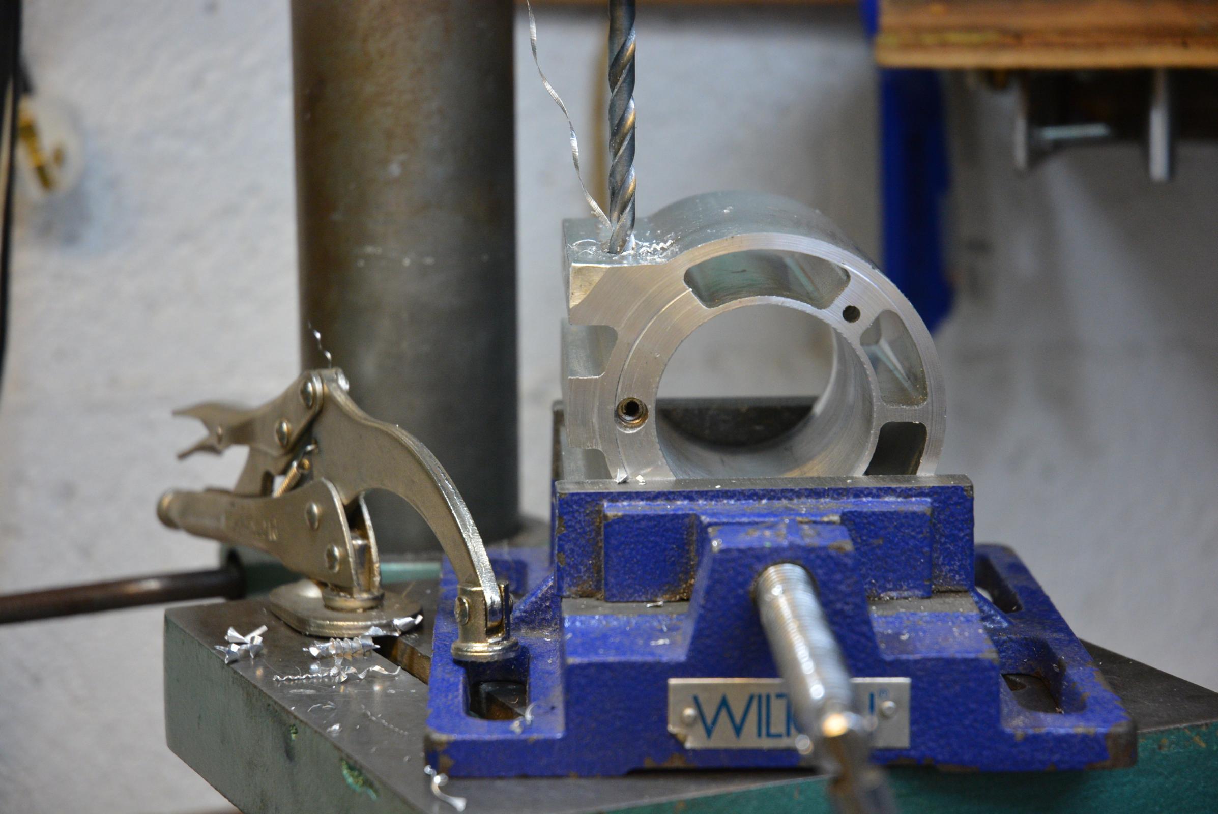
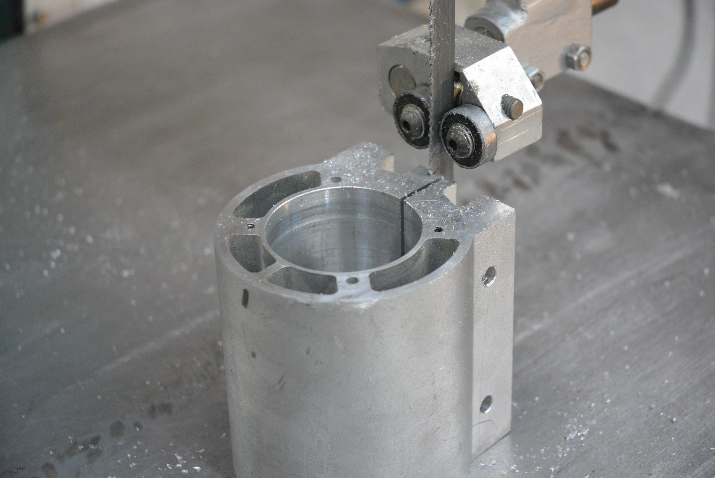
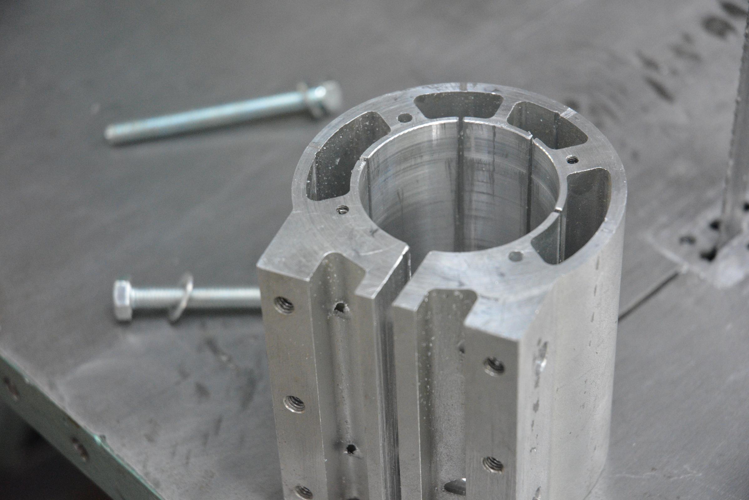
    I had an old aluminium bearing housing in the scrap box which had a bore of 50 mm and the tailstock cylinder was 54 mm so I made a lap by boring out the housing and then splitting it with a bandsaw. I added a couple of clamping screws for adjustment during lapping.

    Cylindrical square from a lathe tailstock.-dsc_2038.jpg Cylindrical square from a lathe tailstock.-dsc_2040.jpg Cylindrical square from a lathe tailstock.-dsc_2041.jpg Click for full size.

    Cylindrical square from a lathe tailstock.-dsc_2045.jpg Cylindrical square from a lathe tailstock.-dsc_2048.jpg Cylindrical square from a lathe tailstock.-dsc_2050.jpg

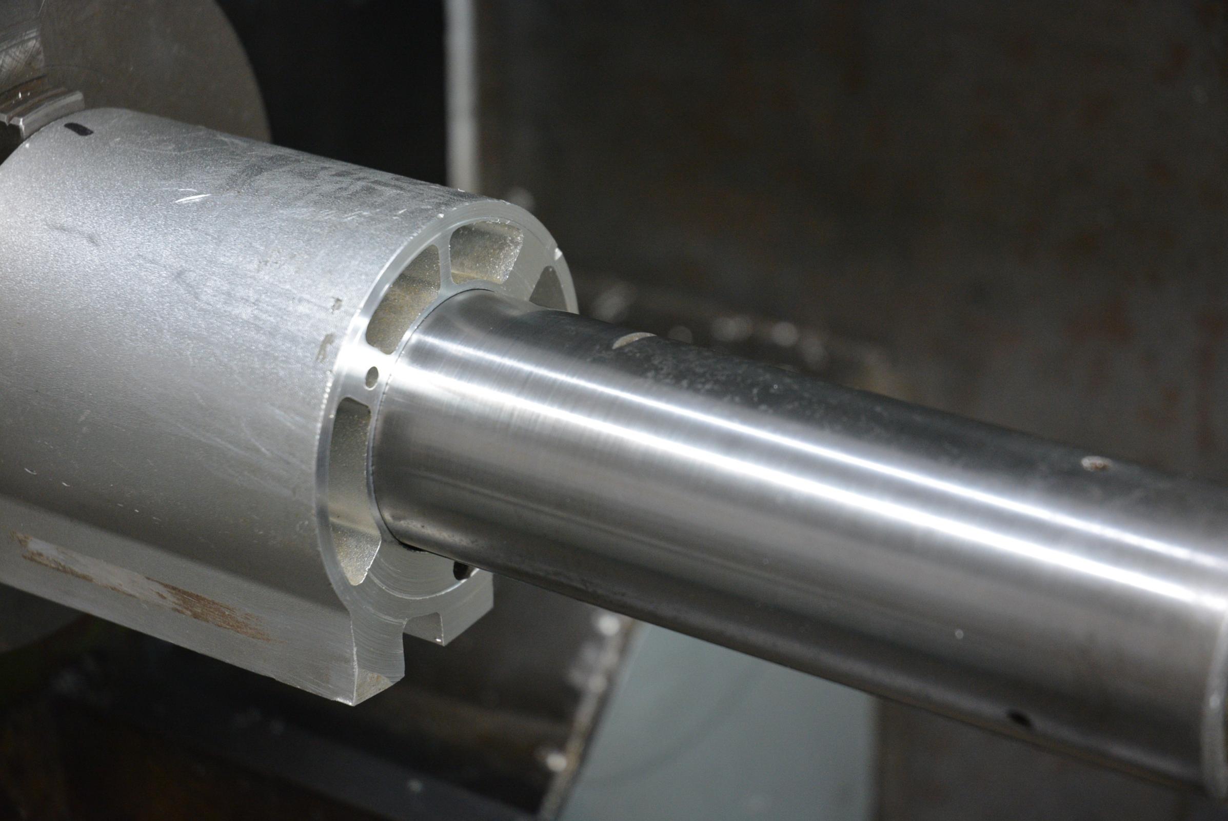
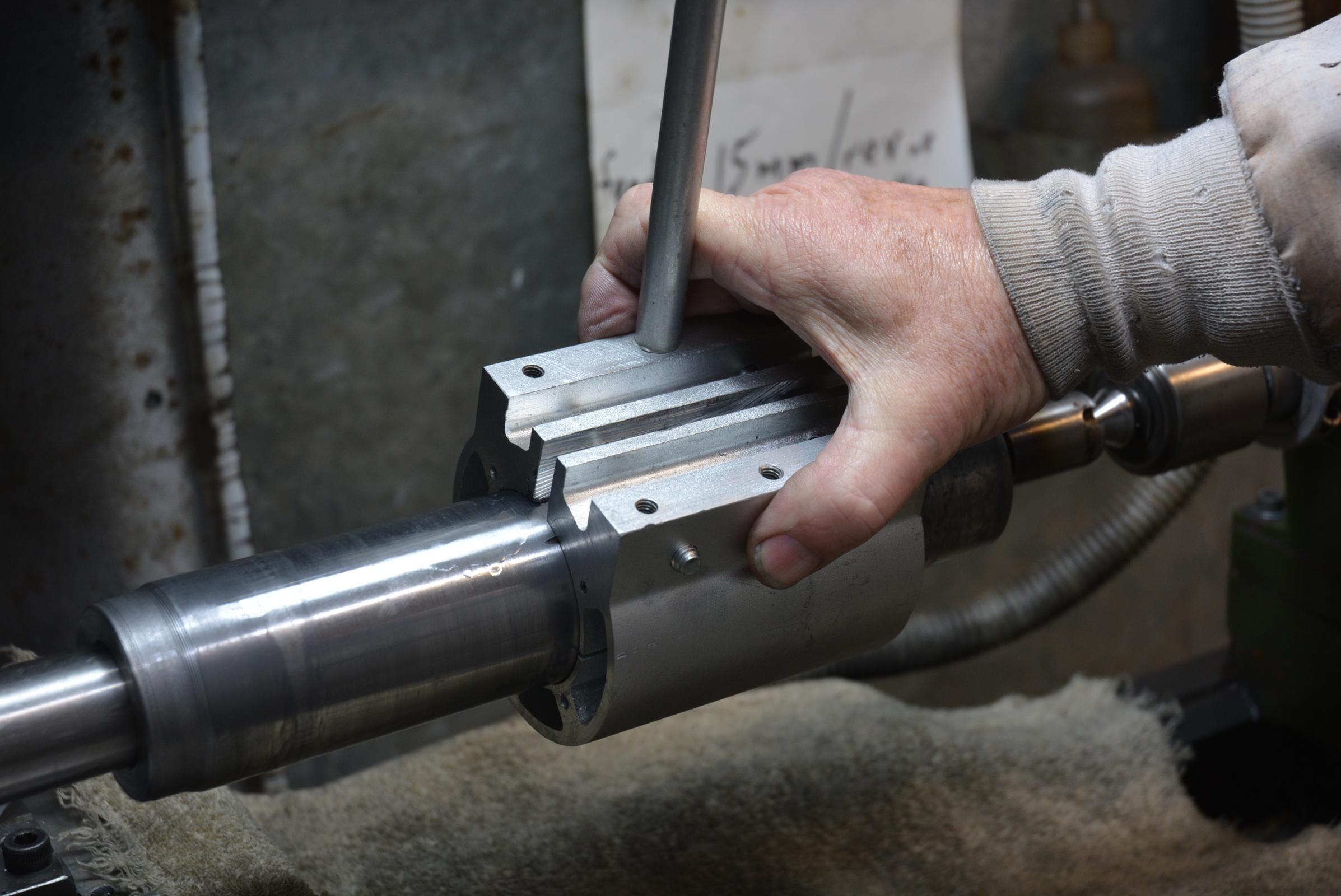
    I had machined the bore for a nice slip fit on the cylinder, but for the initial lapping I spread the diameter a little so that I could charge it with the lapping grit and some thin oil. I worked the lapping over the areas which were the largest. The cylinder varied in diameter by only 2 tenths of a thou. prior to lapping. Pretty good but I like perfection where possible.

    Cylindrical square from a lathe tailstock.-dsc_2058.jpg Lapping.

    After lapping I could detect no difference in diameter over its working length. So that left the squareness to the base to be checked.

    Cylindrical square from a lathe tailstock.-dsc_2067.jpg

    I suggest watching the video for more details. Please like and share it and subscribe to my video channel if you have not already done so.

    186 More Best Homemade Tools eBook

  2. The Following 11 Users Say Thank You to tonyfoale For This Useful Post:

    Carnel (Jan 1, 2020), Corm (Jan 6, 2020), DIYSwede (Dec 31, 2019), emu roo (Nov 24, 2022), johncg (Nov 25, 2022), Jon (Dec 31, 2019), Paul Jones (Jan 1, 2020), Seedtick (Dec 31, 2019), threesixesinarow (Dec 31, 2019), Toolmaker51 (Dec 31, 2019), Tule (Jan 2, 2020)

  3. #2
    Supporting Member tonyfoale's Avatar
    Join Date
    Nov 2016
    Location
    Spain
    Posts
    1,575
    Thanks
    696
    Thanked 2,652 Times in 712 Posts

    tonyfoale's Tools
    Finally I cut a short length off the top to eliminate an undersize area.

    Attachment 32877

    2000 Tool Plans

  4. #3
    Supporting Member DIYSwede's Avatar
    Join Date
    May 2019
    Location
    Stockholm, Sweden...
    Posts
    634
    Thanks
    415
    Thanked 799 Times in 319 Posts

    DIYSwede's Tools
    -Wow! Thanks, Tony for yet another inspiring and educational video!

    You really got the point across regarding the necessity of having a cylinder square:
    its self-checking ability for establishing its own squareness:
    -As even a leaning cylinder have 2 perpendicular lines somewhere around its perimeter...

    For years I've been on the lookout for a 1-ish ft long, 2-3" dia hydraulic piston at scrap yards for precisely this purpose.
    I'll personally try to aim for a 4-5:1 length to dia ratio.

    I was initially a bit hesitant about the compressability of your bearing housing lap,
    but you killed two birds with one stone when slitting the inside, also providing grooves for the slurry...

    Q: I wonder about your sequence of lapping and the grits chosen - any info to share on that, please?

    Turning and lapping in the bottom of the newly sawed-off end will probably be another video of yours?

    All the best for the coming new year!

    Cheers
    Johan

  5. #4
    Supporting Member tonyfoale's Avatar
    Join Date
    Nov 2016
    Location
    Spain
    Posts
    1,575
    Thanks
    696
    Thanked 2,652 Times in 712 Posts

    tonyfoale's Tools
    Quote Originally Posted by DIYSwede View Post
    -Wow! Thanks, Tony for yet another inspiring and educational video!
    For years I've been on the lookout for a 1-ish ft long, 2-3" dia hydraulic piston at scrap yards for precisely this purpose.
    An hydraulic piston shaft should be good, but are they usually hardened or chrome plated? I have never tried lapping chrome.


    Quote Originally Posted by DIYSwede View Post
    Q: I wonder about your sequence of lapping and the grits chosen - any info to share on that, please?
    I do not know the grit size. I have some 1200 grit diamond but that was a bit fine for removing much metal, great for a mirror finish but my concern in this case was not a shiny finish. I had several lots of valve grinding paste and one tube emphasised that the grit was all one size (it did not say what that was), so I used that one. Not a scientific choice but a practical one.[/QUOTE]


    Quote Originally Posted by DIYSwede View Post
    All the best for the coming new year!

    Cheers
    Johan
    Thanks, and the same to all inmates of this forum.

  6. #5
    Supporting Member tonyfoale's Avatar
    Join Date
    Nov 2016
    Location
    Spain
    Posts
    1,575
    Thanks
    696
    Thanked 2,652 Times in 712 Posts

    tonyfoale's Tools
    Quote Originally Posted by DIYSwede View Post
    For years I've been on the lookout for a 1-ish ft long, 2-3" dia hydraulic piston at scrap yards for precisely this purpose.
    Johan
    Your comment reminded me that I happened to have a couple of 20 ton bottle jacks open. i measured them to check what the were like.

    Cylindrical square from a lathe tailstock.-dsc_2084.jpg Click image for full size.

    The item on the right is my new cylindrical square, the other two are from the bottle jacks. The longer one measured up with the ends of equal diameter but around midway was 0.001" large. The shorter one had a gradual taper of 0.003" over its length. Careful setup in a lathe or grinder would allow bringing them up good enough to lap to an accurate shape. Not the ideal donors but they are readily available. The shorter jack was obviously built to lower quality standards, with rougher machining and twisted gaskets etc.

  7. The Following 3 Users Say Thank You to tonyfoale For This Useful Post:

    DIYSwede (Jan 2, 2020), Inner (Jan 4, 2020), Toolmaker51 (Jan 1, 2020)

  8. #6
    Supporting Member Toolmaker51's Avatar
    Join Date
    Feb 2016
    Location
    Midwest USA
    Posts
    5,333
    Thanks
    7,042
    Thanked 2,981 Times in 1,893 Posts

    Toolmaker51's Tools

    Beware! Advancing horde of squares. More acceptable than nerds or wanna-be's.

    DIYSwede, and Tony Foale; very clear you both familiar with geometry that makes Cylinder Squares dependable standards, whether comparison or direct measure.

    To the General Population [inmates], I'll add three, carrying the process off in useful ways.
    Brown & Sharpe [+ others] make a cylinder where ends vary intentionally. One end square isn't any surprise. Their 6" x 2"ish #558 product is OUT OF SQUARE on the other end! What? Yes, intentional! The exterior is marked with ellipses, interpolating out of squareness at given heights. Rotated in proximity with piece being inspected, the tilt goes from possible full contact to less than, regardless. Just as Tony demonstrated and DIYSwede observe, a cylinder [tilted] has two [minimum] perpendicular lines of contact. The #558 can relay needed correction quite accurately; greater angles are likely planned and better verified by sine tools.

    Another fine square, especially popular setting up in accordance with horizontal [vertical plane] locations is the Magnetic Cylinder. Constructing one wouldn't be out of range for many private shops. They are non-magnetic stainless with epoxied Nd magnets [usually 3] with a small gap less than flush from the base. The broad base supports the smaller cylinder readily, as they are machined one piece. Careful handling would make brass, bronze or aluminum rather acceptable.

    Finally, pic might disclose a rarity, the cloverleaf square.
    Cylindrical square from a lathe tailstock.-cyl_squares.jpg
    Some tools arise out of utility.
    Some tools born out of imagination; may not gain interest outside that realm.
    Some go away when processes get outmoded.
    Some disappear, thankfully. We call those gimmicks.

    https://www.google.com/search?q=brow...w=1600&bih=736
    https://www.google.com/search?client...4dUDCAY&uact=5
    Sincerely,
    Toolmaker51
    ...we'll learn more by wandering than searching...

  9. The Following 2 Users Say Thank You to Toolmaker51 For This Useful Post:

    DIYSwede (Jan 1, 2020), tonyfoale (Jan 1, 2020)

  10. #7

  11. The Following User Says Thank You to tonyfoale For This Useful Post:

    Toolmaker51 (Jan 1, 2020)

  12. #8
    Supporting Member Frank S's Avatar
    Join Date
    Aug 2015
    Location
    Peacock TX
    Posts
    11,258
    Thanks
    2,001
    Thanked 8,814 Times in 4,222 Posts

    Frank S's Tools
    Ok there was something I thought I noticed in the My first video that doesn't compute unless the wrist pins have a slight taper to one or the other of them.
    the one that was lapped and showed about a .ooo5 max from zero when he found the center. then with the other pin he had to re zero the gage half way round from the first. I would have thought that you would not re zero your instrument. rather the zero whole have been left alone and the cylinder rotated and moved to locate high center to show either a zero positive or a zero negative at some point on the cylinder baring any cylindrical taper from end to end the indicator should have given a reading of zero, zero there should actually be two 0-0 indications providing the base was perfectly squared and perpendicular to the axis of the indicator in the horizontal plane.
    I used to check cylindrical squareness between 2 cylinders without an indicator on a slab by positioning a true straight edge on the slab weighting it so it could not move push both cylinders against the knifed edge and bring them together with a light behind them then rotate first one then the other until there was zero light shining between them then rotate first one and then the other to find the 2nd zero light position if there happened to be one noting one each where the points of cbest contact occurred. and attempt to lap accordingly.
    Intense light can penetrate even .0000001 and if you have the light shielded so it can only be immitted through a narrow slit in a room with subdued illumination and 2 as near to perfectly ground cylinders as reasonably possible eventually you will wind up with a pair of cylindrical squares.
    There is a way to do this just like the 3 plate lap but for that you need 5 cylinders 2 of which needs to be longer than the 3 and clamped together on laying flat on the slab while you use the 3 to lap against the ends of each other while laying in the v of the 2 longer cylinders. It helps if the 2 longer cylinders have a machined relief in the center of them to allow the lapping compound a place to go that will not contaminant the cylindrical surfaces of either the cylinders having the ends lapped or the 2 cylinders being used as the straight V" surface
    Never try to tell me it can't be done
    When I have to paint I use KBS products

  13. #9
    Supporting Member tonyfoale's Avatar
    Join Date
    Nov 2016
    Location
    Spain
    Posts
    1,575
    Thanks
    696
    Thanked 2,652 Times in 712 Posts

    tonyfoale's Tools
    Quote Originally Posted by Frank S View Post
    Ok there was something I thought I noticed in the My first video that doesn't compute unless the wrist pins have a slight taper to one or the other of them.
    I linked to that video only because it showed the use of large gudgeon pins as cylindrical squares in response to Johan's posts. I could see that it was a tedious video and so I only skimmed through it at double speed with no sound on. Frank, you obviously studied it much closer than I.

  14. #10
    Supporting Member Frank S's Avatar
    Join Date
    Aug 2015
    Location
    Peacock TX
    Posts
    11,258
    Thanks
    2,001
    Thanked 8,814 Times in 4,222 Posts

    Frank S's Tools
    Quote Originally Posted by tonyfoale View Post
    I linked to that video only because it showed the use of large gudgeon pins as cylindrical squares in response to Johan's posts. I could see that it was a tedious video and so I only skimmed through it at double speed with no sound on. Frank, you obviously studied it much closer than I.
    Tony I've never claimed to be one of those ultraprecision machinist but in doing a lot of hydraulic piston pump and valve repairs there were a few tricks I had to try and teach myself. Be they the correct accepted norm or just a hack if I could take a multi thousand dollar assembly and bring it back to 100% serviceability while saving at a minimum of half the cost of replacement was what grew my customer base and brought repeat business
    Never try to tell me it can't be done
    When I have to paint I use KBS products

Thread Information

Users Browsing this Thread

There are currently 1 users browsing this thread. (0 members and 1 guests)

Tags for this Thread

Bookmarks

Posting Permissions

  • You may not post new threads
  • You may not post replies
  • You may not post attachments
  • You may not edit your posts
  •