When I made my dV/dt filter I had a similar problem when I had capacitors as well as inductors. Inductors alone work fine for reducing motor noise and increasing general smoothness.Quote:
Originally Posted by SteelCraft
Printable View
When I made my dV/dt filter I had a similar problem when I had capacitors as well as inductors. Inductors alone work fine for reducing motor noise and increasing general smoothness.Quote:
Originally Posted by SteelCraft
I went to my workshop and checked current during work. Peak is 3.1A when motor is about to stop completely. Normally it drags around 2.1 Amps.
So I should try unsolder capacitors from my filter?Quote:
Inductors alone work fine for reducing motor noise and increasing general smoothness.
Try it. You can always put them back if necessary.Quote:
Originally Posted by SteelCraft
I tried. Without capacitors it just not filtering at all :P
The capacitors need to be sized correctly. They are called snubber capacitors.Quote:
Originally Posted by tonyfoale
https://www.eng-tips.com/threads/snu...697/post-82332
https://fscdn.rohm.com/en/products/d...esign_an-e.pdf
https://www.aosmd.com/res/applicatio..._Reduction.pdf
https://ietresearch.onlinelibrary.wi...-cds.2014.0329
There's plenty of information here to design what you need. Make sure you look for the sections that are for the L-C subbing circuit. The last one at section 3.3 calculates it out, and in the following section calculates against power usage. A little thought of source for higher power inductors is audio, iron laminated cored inductors.
Mark
Filter on the motor side of the VFD? Generally you shouldn't have filters on the motor side of the VFD. Most VFD manuals (industrial or home gamer) say explicitly to not put a filter between the VFD and motor. If you want to install a filter you have to put it on the mains side.Quote:
Originally Posted by SteelCraft
Sorry I should clarify. If you add a boat load of inductance it can overshoot voltage and really do a number on that waveform. Generally VFDs are designed to have absolutely nothing between the VFD and the motor, and it's generally frowned upon to put any filtering between the motor and VFD. If you're getting weird noise and transients filter the mains side of the VFD. Install teck cable on the motor and ground the shield if you're getting interference.
Filters on the motor side are common on bigger motors fed from a VFD. You are only looking at half of the picture. LC filters on the mains side are to reduce feeding VFD noise back into the mains.Quote:
Originally Posted by nova_robotics
The filter on the other side of the VFD is there for another reason. It is called a dV/dt filter, which is the time rate of the voltage build up. This can be noisy and damaging to the motor.
An inductive filter is used to reduce dV/dt, the switching in VFD control causes high values. It is best to keep dV/dt to below 800 to 1200 V/us.
I use both a mains filter on the input and a dV/dt filter on the motor side. The mains filter makes no noticeable difference to anything but I like it there. The dV/dt filter makes a huge difference. See https://www.homemadetools.net/forum/...010#post137780
Long cables to the motor make the problem worse. In severe cases or where a damaged motor would be hard or expensive to replace there are sine wave converters available, these take the PWM signal and turn it into a sinewave with a fraction of the dV/dt values.
This is just not true. VFD makers and suppliers sell and recommend using dV/dt filters and they are strongly suggested for larger motors to avoid shortening motor life.Quote:
Originally Posted by nova_robotics
Fair enough. I stand corrected.Quote:
Originally Posted by tonyfoale
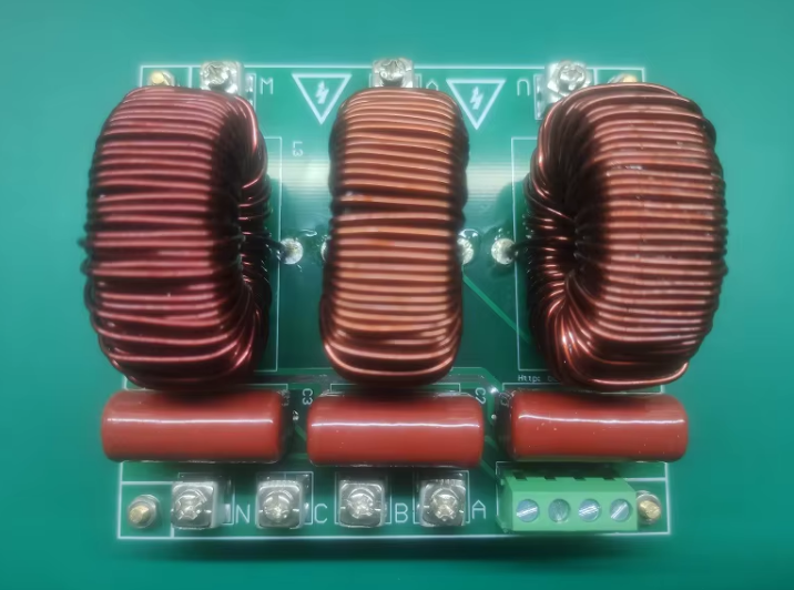
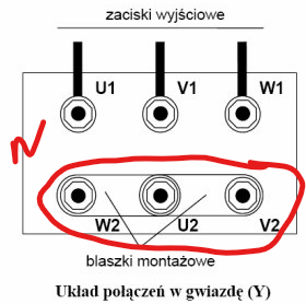
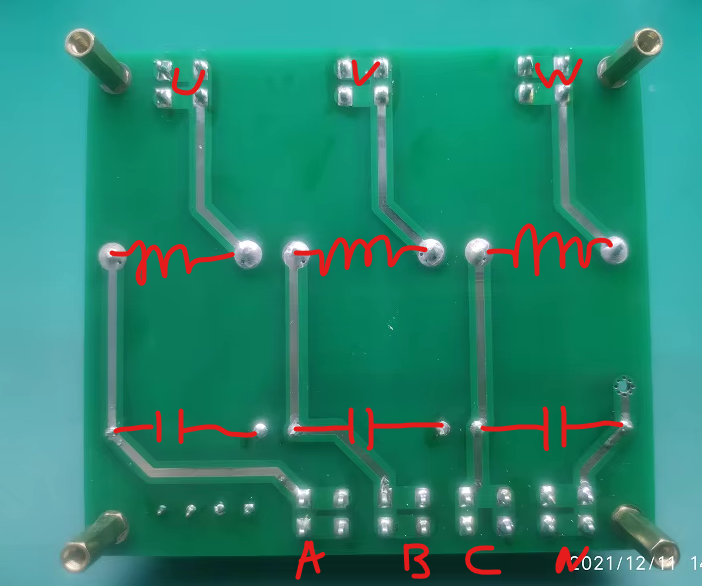
Hi SteelCraft, Can you please post the selfinduction value (L) of the filter coils and the capacity value (C) of the capacitors? And whether each capacitor is connected between two phases or between phase and N?
L for filter coil is 2mH, Capacity value of the capacitor is 4,7uF.
Attachment 49110
Looks like capacitors are connected between phase and N
So the impedance of the coil is 100 Ohms, the capacitor's is 4.25 Ohm. At 8KHz puls frequency the vfd "sees" for the higher frequency pulses an impedance of 96 Ohm and at 230V the filter alone causes a current of 2.4 Amp. That current is 90 degrees out of phase wrt. the voltage and does not consume energy but the vfd has to supply it in addition to the motor current. So Tony's advise to remove the capacitors seems to be a good move. But increasing the inductance of the coils to 50 mH is a better choice. For that latter coil beware of the Ohmic resistance which had to be not to high so the wire OD has to be sufficient. For a 10 Ohm resistance the dissipated power at 2A is 40W and the coil will be heated considerably.
It seems that the base problem here is not understood by some of the respondents. One major cause is the capacitance of the cables to the motor. This is why long cable runs are more in need of inductive dV/dt filters and why added capacitance is usually unhelpful.
Is the filter installed between the line and the VFD?
The filter under most discussion here is a dV/dt filter between the VFD and motor. A line filter may also be installed on the input side of the VFD. The two filters perform very different jobs.Quote:
Originally Posted by jraymjr
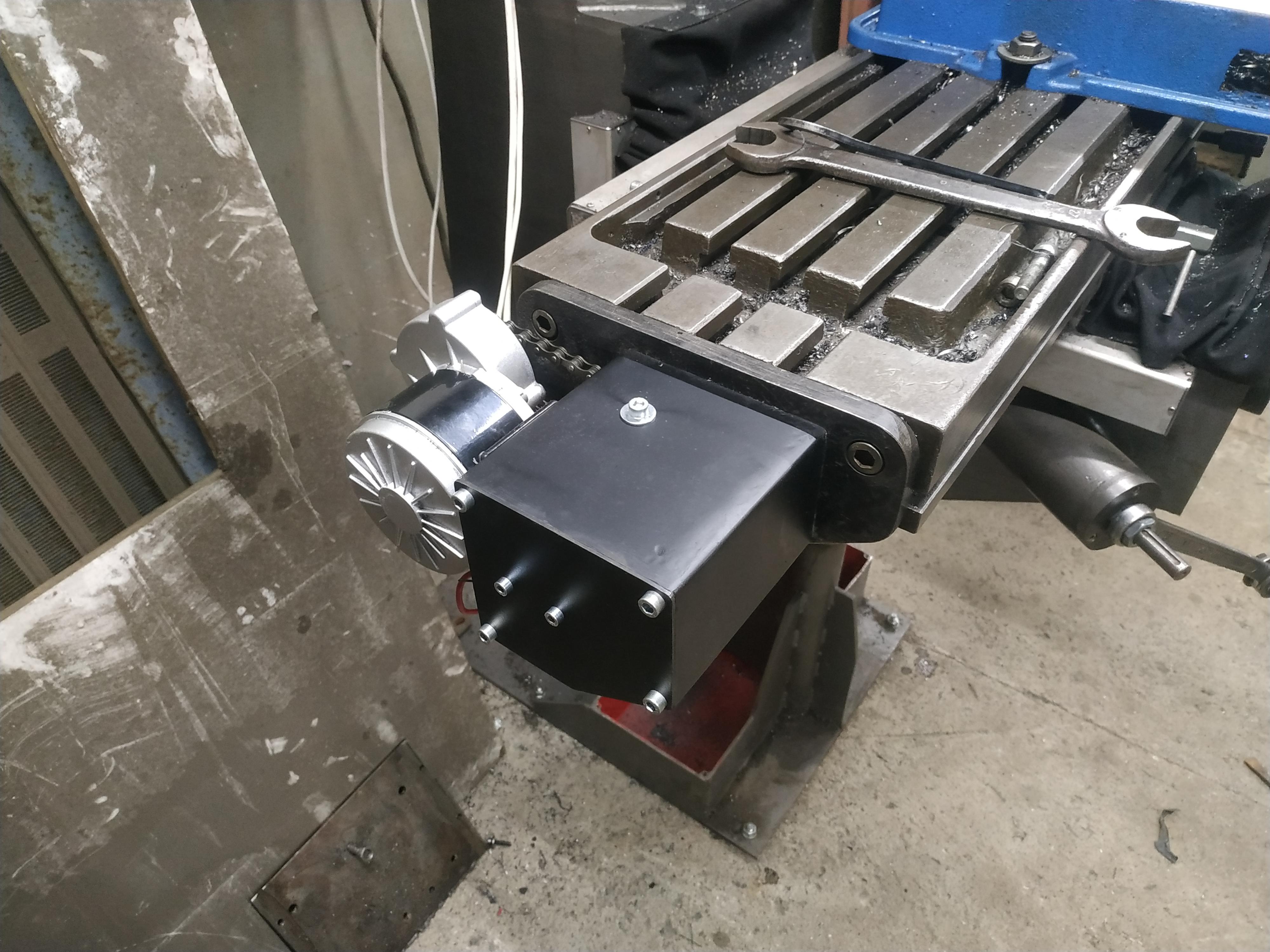
Project is moving forward to power feeds.
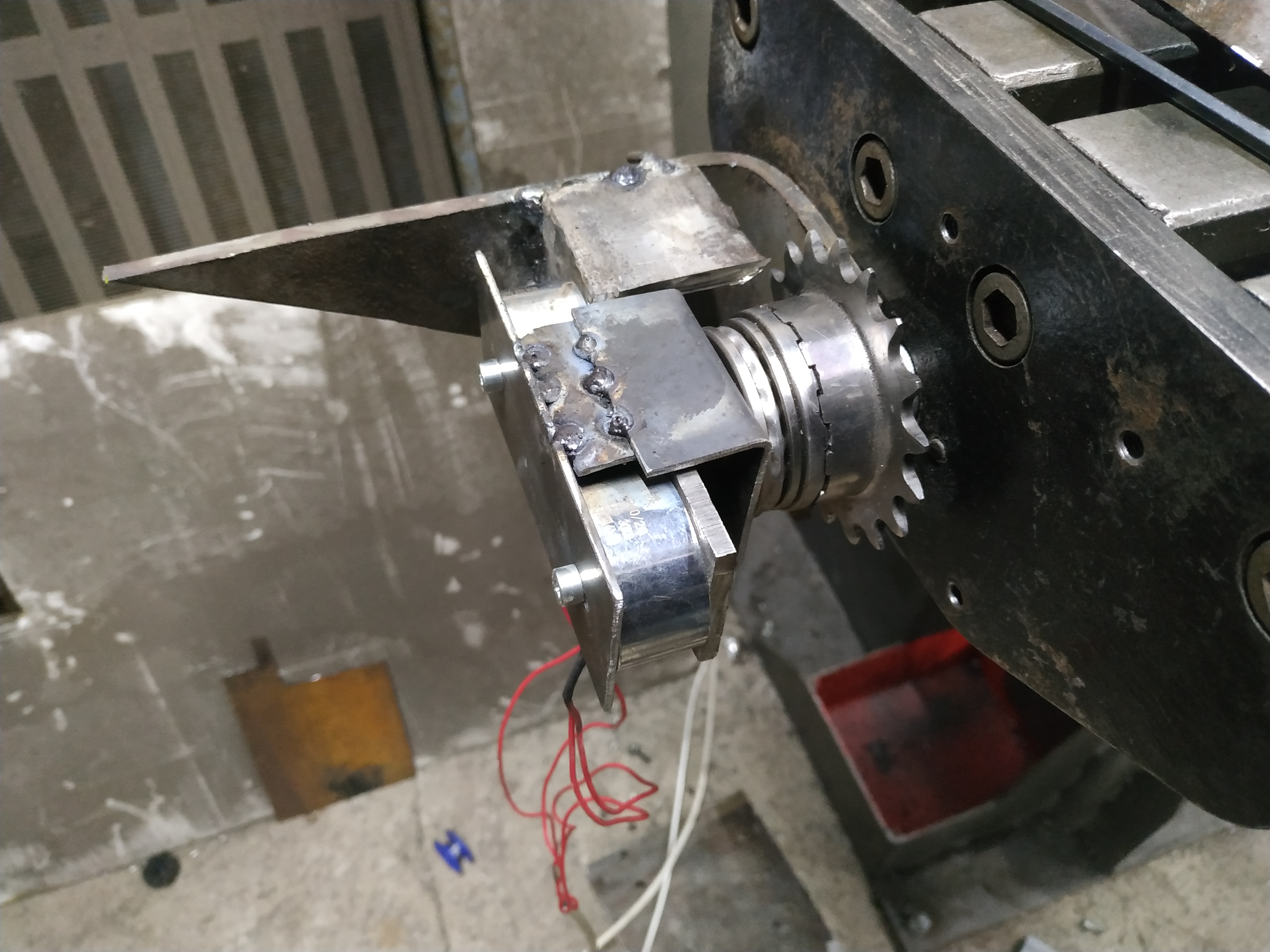
This is crappy prototype to find out if idea was good. There are two halves of dog clutch, spring between them. Electromagnets connects both halves together, distance of movement is only 2.5 [mm]. Why I build whole clutch by myself and didn't use a car air conditioner electromagnetic clutch? - Clutch from AC is huge.
Attachment 49308
Then I built nice civilised looking unit:
Attachment 49309
Now I'm going to build similar working clutches for Y and Z axis.
I have used clutches from car AC on a lathe spindle motor, but as you say they are too large to be suitable for axes drives.Quote:
Originally Posted by SteelCraft
What happens when the two halves of the dog clutch try to come together with a high tooth against a high tooth? Does it just spin until the two halves fit together? Do you activate the clutch before the drive motor or are they activated together?
It spins until two halves fit together. Clutch is activated when PWM module is switched on, motor activation is not possible with clutch deactivated.Quote:
Originally Posted by tonyfoale
I built similar working power feed for Z axis and I faced a problem which made me stuck.
Lead screw nut (made from bronze) when knee going down starts vibrating a lot. Very loud, whole machine starts shaking. I tried everything even welding in again flange for nut to remove any missaligment but nothing helped.
It worked well only two days...
Lead screw don't run dry, it's oiled.
Do you have any ideas what else I could try to remove those vibration?
Problem on video:
https://www.youtube.com/watch?v=z0qpzddXsZk
So for two days of use after you allowed for the re-alignment you had good turning, and then back to vibration?Quote:
Originally Posted by SteelCraft
Więc przez dwa dni użytkowania, po ponownym wyregulowaniu nakrętki, obroty były dobre, a potem znów pojawiły się wibracje?
Mark
Two days of use were after first assembly and tests. When I do re-alignment of nut everything is messed after one - two cycles up and down.Quote:
Originally Posted by mwmkravchenko
IIRC you have linear ball slides on the Z axis, that is very low friction. I am guessing but I do not believe this is a good match to a normal lead screw. Maybe you need a ball screw. Like I said this is a guess, but the forces provided by the slide friction from normal dovetails will relieve load off the lead screw and nut on the way down.Quote:
Originally Posted by SteelCraft
I am currently building a CNC surface grinder which with a change of grinding head to a milling spindle will also be a 3 axes mill. I am using linear rails and ball screws on each axis. However as it is a work in progress it is too early to come to any conclusions about vibration. I have my fingers crossed.
Here is an idea. On my Bridgeport mill I have added 4 assist springs to the knee to relieve load off the stock screw and nut. Here is post that I made https://www.homemadetools.net/forum/knee-helper-55951
maybe something like that would work for you???????
Problem solved :D
Resonance was caused by slightly too loose chain between motor and clutch. I put more tension and all weird symptoms are gone.
So this is loose chain on your power feed?Quote:
Originally Posted by SteelCraft
And yes a resonance can do this. The other thing that may allow it is incorrect lubricant. Perhaps a light wheel bearing grease on the screw and nut?
Mark
I use LAN-46 machine oil, meant for gearboxes, hydraulics and slide guide ways.Quote:
Originally Posted by mwmkravchenko
New Video:
Part 19 Building power feed for all axis:
https://youtu.be/koU8gmQvLwE
Hello
I added flood coolant to my DIY milling machine. It's build to be easily replaceable.
https://youtu.be/eaR0CrmyHlk
<!-- BEGIN /var/www/html/homemadetools/protected/modules/zeus/views/tool/postUpdate.php -->
Thanks SteelCraft! We've added your Flood Coolant System to our Machining category,
as well as to your builder page: SteelCraft's Homemade Tools. Your receipt:
<div id="blocks"> <div class="block b1 pngfix"> <div class="bimg"> <div> <a href="https://www.homemadetools.net/homemade-flood-coolant-system-2"> <img src="/uploads/276275/homemade-flood-coolant-system-2.jpeg"/> </a> </div> </div> <div class="head pngfix"></div> <div class="left pngfix"></div> <div class="right pngfix"></div> <div class="blockover b1 pngfix"> <div class="title"> <a href="https://www.homemadetools.net/homemade-flood-coolant-system-2">Flood Coolant System</a> <span> by <a href="https://www.homemadetools.net/builder/SteelCraft">SteelCraft</a></span> </div> <div class="tags">tags: <a href='https://www.homemadetools.net/tag/coolant'>coolant</a> </div> </div> </div> </div>
<!-- END /var/www/html/homemadetools/protected/modules/zeus/views/tool/postUpdate.php -->
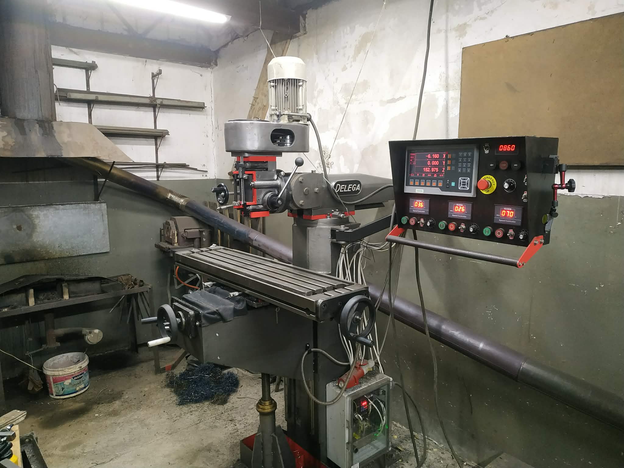
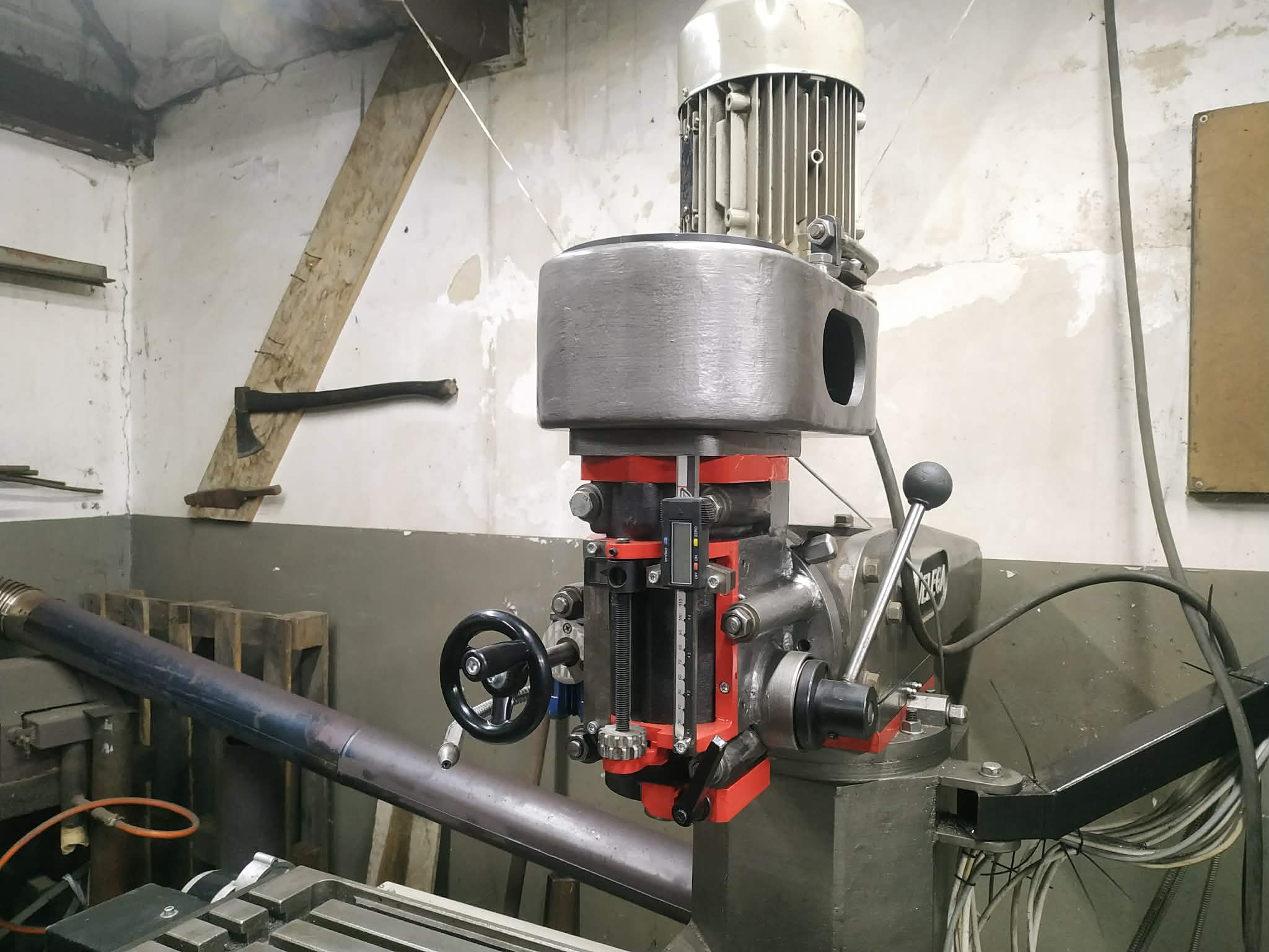
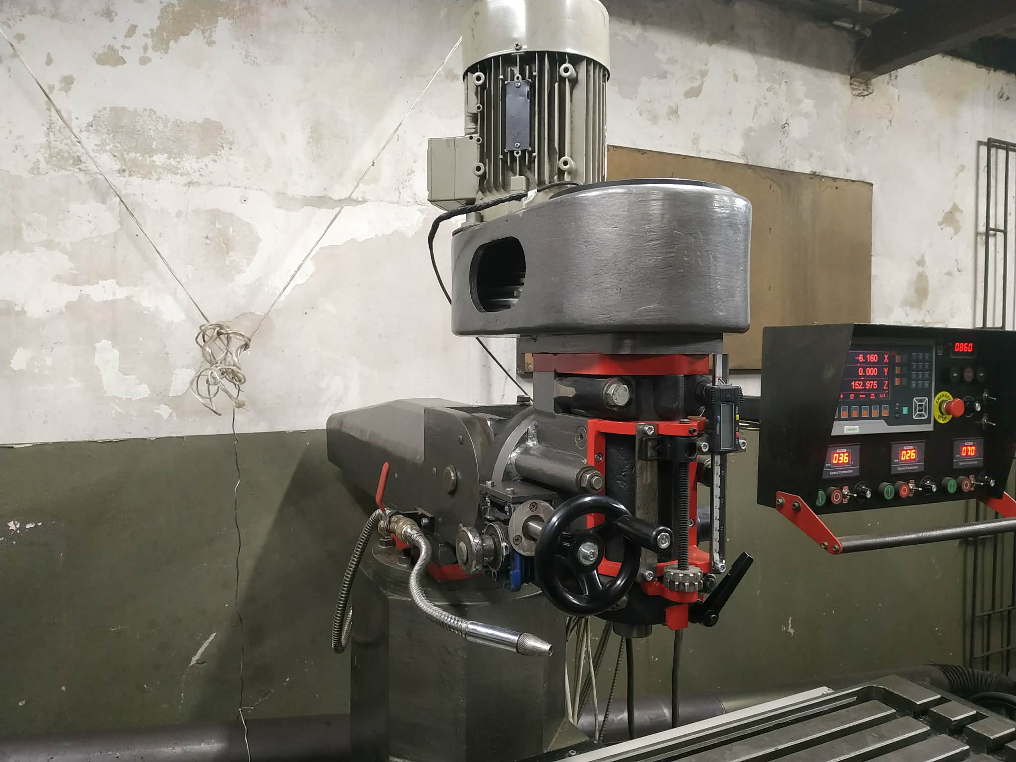
Hello!
I finally managed to finish build of new improved head for my milling machine. Let's say it's third version but second one existed only as 3d model.
Quill, motor, pulleys, fine feed worm gearbox are from old head. Still needs some tweaks before recording test and publishing built video.
Attachment 50255
Attachment 50254
Attachment 50253
Hopefully I will change current mt3 spindle shaft to custom made iso30 taper spindle shaft and then install power drawbar.
The spindle change is a good move. I always wondered why you didn't pick R8 or iso30 instead of MT3.Quote:
Originally Posted by SteelCraft
There is a contributor on this forum "ThreadExpress" who did a very interesting comparison of R8 and iso30. He may have included a MT3 but I do not remember exactly.
MT3 spindle was dirt cheap on aliexpress, literally 50 USD. Back then I didn't know if whole machine will even work as mill and plan B was fancy drill press - that's all.Quote:
Originally Posted by tonyfoale
That is a pretty good reason. Did you ever measure the runout on that spindle?Quote:
Originally Posted by SteelCraft
You have built something way beyond a fancy drill press.
Here is a link to the ThreadExpress video comparison between R8, TTS and iso30.Quote:
Originally Posted by tonyfoale
Yes, I did it in the end of very first episode of this series. Needle barely moved in range of less than 0.01 [mm] inside taper.Quote:
Originally Posted by tonyfoale
That is pretty good for a $50 spindle.Quote:
Originally Posted by SteelCraft
Improved machine head build video:
https://youtu.be/Zbl7crmkgZw
Awesome work!Quote:
Originally Posted by tonyfoale
Oops, it looks like I forgot to include the link. Here it is https://www.youtube.com/watch?v=m9rMbSLyAvMQuote:
Originally Posted by tonyfoale
New video:
Finally I got nice NT30 spindle. No more abusing my mill with the hammer when changing the tool :)
https://youtu.be/DWM35D9nLjw?si=tadIMchhJ4q28BNT
Powerdrawbar is next ;)