 LinkBack URL
 About LinkBacks
When I made my dV/dt filter I had a similar problem when I had capacitors as well as inductors. Inductors alone work fine for reducing motor noise and increasing general smoothness.Originally Posted by SteelCraft


When I made my dV/dt filter I had a similar problem when I had capacitors as well as inductors. Inductors alone work fine for reducing motor noise and increasing general smoothness.
philippacificnw (Apr 26, 2025), SteelCraft (Apr 19, 2025)

I went to my workshop and checked current during work. Peak is 3.1A when motor is about to stop completely. Normally it drags around 2.1 Amps.
So I should try unsolder capacitors from my filter?Inductors alone work fine for reducing motor noise and increasing general smoothness.
Try it. You can always put them back if necessary.
philippacificnw (Apr 26, 2025)
I tried. Without capacitors it just not filtering at all :P

The capacitors need to be sized correctly. They are called snubber capacitors.
https://www.eng-tips.com/threads/snu...697/post-82332
https://fscdn.rohm.com/en/products/d...esign_an-e.pdf
https://www.aosmd.com/res/applicatio..._Reduction.pdf
https://ietresearch.onlinelibrary.wi...-cds.2014.0329
There's plenty of information here to design what you need. Make sure you look for the sections that are for the L-C subbing circuit. The last one at section 3.3 calculates it out, and in the following section calculates against power usage. A little thought of source for higher power inductors is audio, iron laminated cored inductors.
Mark
philippacificnw (Apr 26, 2025), SteelCraft (Apr 26, 2025)
Filter on the motor side of the VFD? Generally you shouldn't have filters on the motor side of the VFD. Most VFD manuals (industrial or home gamer) say explicitly to not put a filter between the VFD and motor. If you want to install a filter you have to put it on the mains side.
Sorry I should clarify. If you add a boat load of inductance it can overshoot voltage and really do a number on that waveform. Generally VFDs are designed to have absolutely nothing between the VFD and the motor, and it's generally frowned upon to put any filtering between the motor and VFD. If you're getting weird noise and transients filter the mains side of the VFD. Install teck cable on the motor and ground the shield if you're getting interference.
Last edited by nova_robotics; Apr 22, 2025 at 02:56 PM.
mwmkravchenko (Apr 22, 2025), philippacificnw (Apr 26, 2025)
Filters on the motor side are common on bigger motors fed from a VFD. You are only looking at half of the picture. LC filters on the mains side are to reduce feeding VFD noise back into the mains.
The filter on the other side of the VFD is there for another reason. It is called a dV/dt filter, which is the time rate of the voltage build up. This can be noisy and damaging to the motor.
An inductive filter is used to reduce dV/dt, the switching in VFD control causes high values. It is best to keep dV/dt to below 800 to 1200 V/us.
I use both a mains filter on the input and a dV/dt filter on the motor side. The mains filter makes no noticeable difference to anything but I like it there. The dV/dt filter makes a huge difference. See Stuff about VFDs and motors
Long cables to the motor make the problem worse. In severe cases or where a damaged motor would be hard or expensive to replace there are sine wave converters available, these take the PWM signal and turn it into a sinewave with a fraction of the dV/dt values.
This is just not true. VFD makers and suppliers sell and recommend using dV/dt filters and they are strongly suggested for larger motors to avoid shortening motor life.
mwmkravchenko (Apr 22, 2025), nova_robotics (Apr 22, 2025), philippacificnw (Apr 26, 2025), SteelCraft (Apr 26, 2025)

Fair enough. I stand corrected.
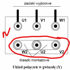
 of the filter coils and the capacity value (C) of the capacitors? And whether each capacitor is connected between two phases or between phase and N? "Pin It")
Hi SteelCraft, Can you please post the selfinduction value (L) of the filter coils and the capacity value (C) of the capacitors? And whether each capacitor is connected between two phases or between phase and N?
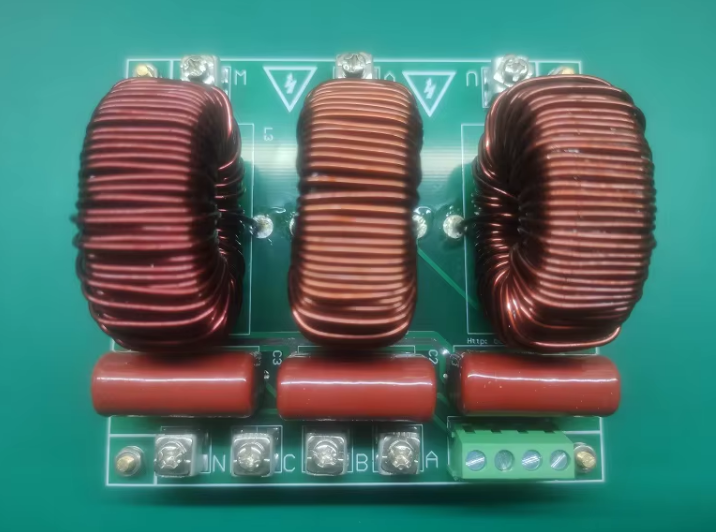
L for filter coil is 2mH, Capacity value of the capacitor is 4,7uF.
Looks like capacitors are connected between phase and N
There are currently 2 users browsing this thread. (0 members and 2 guests)
 Posting Permissions


 Reply With Quote
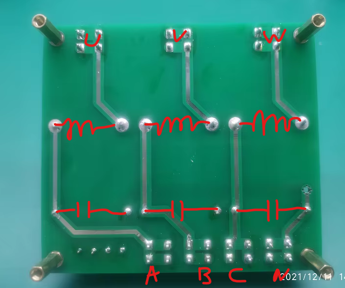
Bookmarks