Free 186 More Best Homemade Tools eBook:  
New: 300+ fresh build posts/day from 275 forums → BuildThreads.com

User Tag List

Page 1 of 3 1 2 3 LastLast
Results 1 to 10 of 28

Thread: Miniature die filer

Hybrid View

  1. #1
    Supporting Member mklotz's Avatar
    Join Date
    Aug 2015
    Location
    LA, CA, USA
    Posts
    3,720
    Thanks
    376
    Thanked 7,194 Times in 2,349 Posts

    mklotz's Tools

    Miniature die filer

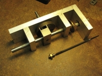
    I haven't found anyone yet who wants to donate me their die filing machine so I resorted to building a miniature version for myself. Like its big brother it uses a Scotch Yoke arrangement to turn circular motion into reciprocating motion, driving a file up and down through a hole in its table. In use, a workpiece is held against the file to debur and/or final shape. Beyond relieving the operator of physical effort, it has the advantage of producing nice, crisp, orthogonal surfaces on pieces with curved edges.

    Here's the basic machine showing the drive. A diamond file is mounted and next to the machine is a conventional file which has been modified to be used in the machine. Die filers cut on the down stroke to avoid lifting the part from the table so, to adapt a conventional file one must provide a way of mounting it from its outboard end. In this case I've soldered a bit of threaded rod to the file end and added a lock nut to keep it firmly attached to the driver.


    Here's another view. The brass disk under the file attach point is there to deflect swarf and keeping it from falling into the bearings.


    Another view showing the drive shaft. Normally I grasp it in the bench vise and power it via a flexible cable from an electric drill. It works nicely for my small stuff but I'll still accept donations of a manly die filer. [There is a company that sells castings for one but I haven't gone there yet.]


    Last edited by mklotz; Jul 6, 2017 at 11:10 AM.
    ---
    Regards, Marv

    Smart phones are to people what laser pointers are to cats
    Homo sapiens is a goal, not a definition

  2. The Following 23 Users Say Thank You to mklotz For This Useful Post:

    12L14 (Jul 31, 2019), Altair (Nov 13, 2019), bobs409 (Feb 19, 2017), Canyonman44 (Aug 5, 2021), emu roo (Aug 4, 2021), HobieDave (Mar 13, 2020), Home-PC (Aug 6, 2021), Inner (Feb 10, 2018), jjr2001 (Apr 17, 2017), kbalch (Sep 3, 2015), Kevic (Jun 15, 2018), Mark Fogleman (Jun 15, 2018), Moby Duck (Feb 10, 2018), Murph1090 (Feb 10, 2018), old_toolmaker (Jun 21, 2019), Paul Jones (Sep 3, 2015), philipUsesWood&Brass (Jun 30, 2018), PJs (Sep 4, 2015), Raytonian (Sep 26, 2021), rendoman (Feb 11, 2018), rgsparber (Aug 4, 2021), Stevohdee (Jun 14, 2018), volodar (Jun 14, 2018)

  3. #2
    kbalch's Avatar
    Join Date
    Jun 2012
    Location
    Clermont, FL
    Posts
    5,034
    Thanks
    2,275
    Thanked 666 Times in 482 Posts
    Thanks Marv! I've added your Miniature Die Filer to our Filing category, as well as to your builder page: mklotz's Homemade Tools. Your receipt:


  4. The Following User Says Thank You to kbalch For This Useful Post:

    emu roo (Feb 27, 2026)

  5. #3

    Join Date
    Jan 2016
    Posts
    2
    Thanks
    0
    Thanked 1 Time in 1 Post
    Thanks for sharing, BUT for those of us who do not already have a similar device, the posted description is frustratingly confusing. I cannot tell where the work is placed or attached or held steady; evidently there is a conversion of rotary motion to reciprocating, but it's not clear how the rotary motion is attached or created, nor where the conversion to reciprocating occurs. A large round brass/copper plug of some kind is apparently adjacent to a hole in the ?base? of similar diameter, but I cannot tell how that relates.

    Somehow 50 years of casual amateur fabrication on my 9" South Bend thread-turning lathe has not equipped me to figure out how the device works; with all due respect, I suggest that the pictures and description would benefit from having about 50% more detail, perhaps with a diagram of inputs and outputs, for the newcomer to diemaking . . . we all tend to gloss over a few steps and details of mechanisms with which we deal on a daily basis, just need to step back a little and look at our work from a newcomer's perspective to ensure clarity. Certainly the workmanship IS of superior quality, nice work!

  6. The Following User Says Thank You to pa42 For This Useful Post:

    emu roo (Feb 27, 2026)

  7. #4
    Supporting Member mklotz's Avatar
    Join Date
    Aug 2015
    Location
    LA, CA, USA
    Posts
    3,720
    Thanks
    376
    Thanked 7,194 Times in 2,349 Posts

    mklotz's Tools
    Quote Originally Posted by pa42 View Post
    Thanks for sharing, BUT for those of us who do not already have a similar device, the posted description is frustratingly confusing. I cannot tell where the work is placed or attached or held steady; evidently there is a conversion of rotary motion to reciprocating, but it's not clear how the rotary motion is attached or created, nor where the conversion to reciprocating occurs. A large round brass/copper plug of some kind is apparently adjacent to a hole in the ?base? of similar diameter, but I cannot tell how that relates.

    Somehow 50 years of casual amateur fabrication on my 9" South Bend thread-turning lathe has not equipped me to figure out how the device works; with all due respect, I suggest that the pictures and description would benefit from having about 50% more detail, perhaps with a diagram of inputs and outputs, for the newcomer to diemaking . . . we all tend to gloss over a few steps and details of mechanisms with which we deal on a daily basis, just need to step back a little and look at our work from a newcomer's perspective to ensure clarity. Certainly the workmanship IS of superior quality, nice work!
    As stated in the description, the drive mechanism is a Scotch yoke. This is a common mechanism for translating rotary motion to reciprocating. Details of the design can be easily found by typing "Scotch yoke" into Wikipedia, which would lead you here...

    https://en.wikipedia.org/wiki/Scotch_yoke

    The rotary motion can be supplied by any source that produces rotary motion. As stated in the description I use an electric hand drill with a flexible shaft but a dedicated motor with belt and pullies is also possible.

    As stated in the description, the brass plate under the hole in the table is there to divert filing swarf away from the bearings and drive yoke mechanism. Most die filers have something similar.
    Last edited by mklotz; Feb 19, 2017 at 05:29 PM.
    ---
    Regards, Marv

    Smart phones are to people what laser pointers are to cats
    Homo sapiens is a goal, not a definition

  8. The Following User Says Thank You to mklotz For This Useful Post:

    emu roo (Feb 27, 2026)

  9. #5
    Supporting Member
    Join Date
    Aug 2016
    Posts
    635
    Thanks
    1
    Thanked 269 Times in 225 Posts

    wizard69's Tools
    The good news is that there are at least two companies selling die filer casting kits that I know of, one being Martin Model and pattern, the other being Metal Lathe. Each has a unique take on the machine but I wouldn't consider any of them to be manly. At least not in the sense of the old iron that can be found out there from a time when die filers where an important part of a machine shop.

    I suspect that a machine built from stock would be just as good as one built from castings.

  10. The Following User Says Thank You to wizard69 For This Useful Post:

    emu roo (Feb 27, 2026)

  11. #6
    Supporting Member Paul Jones's Avatar
    Join Date
    May 2014
    Location
    Del Mar, California
    Posts
    1,232
    Thanks
    5,823
    Thanked 1,654 Times in 740 Posts

    Paul Jones's Tools
    Thank you for the reference to Martin Model and Pattern for the die filer.

    I remember seeing the Martin Model and Pattern castings and plans for a Quorn Universal Tool & Cutter Grinder and it always looked very interesting. I sometimes wonder which approach would be better: 1) building the universal tool and cutter grinder from castings; or 2) for a few hundred dollars more, buying an import equivalent machine tool and then improving the import?

  12. The Following User Says Thank You to Paul Jones For This Useful Post:

    emu roo (Feb 27, 2026)

  13. #7
    Supporting Member
    Join Date
    Aug 2016
    Posts
    635
    Thanks
    1
    Thanked 269 Times in 225 Posts

    wizard69's Tools
    Quote Originally Posted by Paul Jones View Post
    Thank you for the reference to Martin Model and Pattern for the die filer.

    I remember seeing the Martin Model and Pattern castings and plans for a Quorn Universal Tool & Cutter Grinder and it always looked very interesting. I sometimes wonder which approach would be better: 1) building the universal tool and cutter grinder from castings; or 2) for a few hundred dollars more, buying an import equivalent machine tool and then improving the import?
    The Quorn is very interesting but it strikes me as a very light weight machine. It is built with lots of bar stock and just doesn't give me that warm fuzzy feeling. Given that if you build one you certainly have bragging rights considering it would be a big accomplishment. There are also lots of alternative tool grinder designs that float about the model engineering magazines.

    Personally I think you would be better off going the used or import route if you wanted a full tool grinder. Yes rebuilding is likely, but careful searching can turn up some good deals for used equipment. Other wise a few fixtures and a bench grinder or two are far more economical.

  14. The Following 2 Users Say Thank You to wizard69 For This Useful Post:

    emu roo (Feb 27, 2026), Paul Jones (Feb 21, 2017)

  15. #8
    Supporting Member tonyfoale's Avatar
    Join Date
    Nov 2016
    Location
    Spain
    Posts
    1,821
    Thanks
    834
    Thanked 3,242 Times in 910 Posts

    tonyfoale's Tools
    Quote Originally Posted by wizard69 View Post
    The Quorn is very interesting but it strikes me as a very light weight machine. It is built with lots of bar stock and just doesn't give me that warm fuzzy feeling.
    i toyed with the idea of making something like the Quorn before I built something completely different shown here http://www.homemadetools.net/forum/h...fference-56205

    The Quorn was designed to be made on a small lathe with a milling slide hence its small size. If you read the post on mine you will see that you can make something much simpler with less degrees of angular freedom without losing any function.

    For those unfamiliar with the Quorn here is a pic.

    Miniature die filer-quorn.jpg

    The Quorn was sold as a plans kit and/or a set of castings to be machined. As each Quorn is homemade they all are slightly different usually incorporating the constructor's own ideas. For example the one pictured uses an ER collet holder which was not in the original plans.

  16. The Following 2 Users Say Thank You to tonyfoale For This Useful Post:

    emu roo (Feb 27, 2026), Home-PC (Aug 6, 2021)

  17. #9
    Supporting Member
    Join Date
    Aug 2016
    Posts
    635
    Thanks
    1
    Thanked 269 Times in 225 Posts

    wizard69's Tools
    Quote Originally Posted by tonyfoale View Post
    i toyed with the idea of making something like the Quorn before I built something completely different shown here http://www.homemadetools.net/forum/h...fference-56205

    The Quorn was designed to be made on a small lathe with a milling slide hence its small size. If you read the post on mine you will see that you can make something much simpler with less degrees of angular freedom without losing any function.
    Interesting machine you got there Tony! My point wasn't to dismiss the Quorn but just point out that there are many designs floating about the net these days for tool grinders, some could be called more robust. Yours is an interesting design so I have to ask, do you have a web site detailing its construction or design?

    For those unfamiliar with the Quorn here is a pic.

    Click image for larger version. 

Name:	Quorn.JPG 
Views:	1140 
Size:	46.6 KB 
ID:	16706

    The Quorn was sold as a plans kit and/or a set of castings to be machined. As each Quorn is homemade they all are slightly different usually incorporating the constructor's own ideas. For example the one pictured uses an ER collet holder which was not in the original plans.
    Building to suit your needs is one of the great rewards of the DIY culture.

  18. #10
    Supporting Member tonyfoale's Avatar
    Join Date
    Nov 2016
    Location
    Spain
    Posts
    1,821
    Thanks
    834
    Thanked 3,242 Times in 910 Posts

    tonyfoale's Tools
    Quote Originally Posted by wizard69 View Post
    Interesting machine you got there Tony! ......... Yours is an interesting design so I have to ask, do you have a web site detailing its construction or design?
    My web site address, blog & Facebook are listed below in my signature.
    However the only documentation that I have done for it is what you see on this forum, but there was another post on here showing more detail of the base machine which you can see at http://www.homemadetools.net/forum/h...-machine-55333
    Between that and the main description there is plenty of detail. I almost never draw anything before making and so I have no plans to offer.

Thread Information

Users Browsing this Thread

There are currently 1 users browsing this thread. (0 members and 1 guests)

Bookmarks

Posting Permissions

  • You may not post new threads
  • You may not post replies
  • You may not post attachments
  • You may not edit your posts
  •