
 LinkBack URL
 About LinkBacks


My first post on this forum outlined how I inverted a cheap bottle jack to use in a workshop press. See here for full description : http://www.homemadetools.net/forum/i...5188#post81319
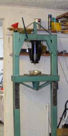
Just for completeness here are a couple of pictures of the original upsidedown modified jack. Click for full size picture.
A couple of weeks after building the press it occurred to me that as there were only two connections to the working cylinder. One is the low pressure external connection to dump fluid when the ram is retracted. The other is a high pressure internal connection to the pump but the inlet to the pump is accessible and I had already accessed that for the current jack inversion.
My new idea was to use the jack without its outside cover which acted as a reservoir for the fluid. I would just need to make a hose connection to the exhaust outlet and connect that and the pump inlet to an external tank. However, my existing modifications were working fine and so there was no pressing motivation to modify further. That was until recently when after a period of non-use most of the oil had leaked on to the floor creating a hell of a mess. Hydraulic oil is very slippery and harder to clean up than normal engine oil for example. I obviously had to look inside the jack and so it seemed like the ideal opportunity to implement the planned system. I also decided to hone the cylinder while it was accessible. That adventure is detailed here :
http://www.homemadetools.net/forum/i...769#post102422
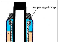
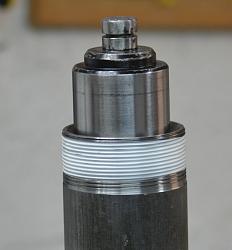
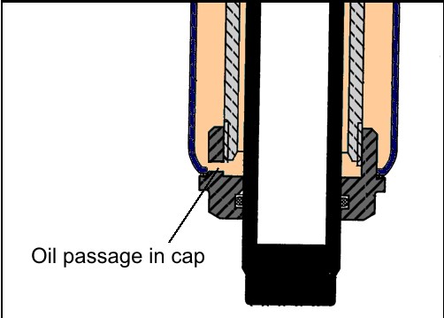
For those unfamiliar with the internals of common bottle jacks here is a sketch showing the basic construction. Note that the ram has a slightly smaller diameter than the piston and cylinder, so there is a small air gap between the cylinder wall and the ram. As the ram is extended that air volume is reduced. To avoid pressure build up that air is vented to the outer reservoir via a hole in the top cap. Although I said that there was air in the gap there could also be some oil which has leaked past the main piston seal.
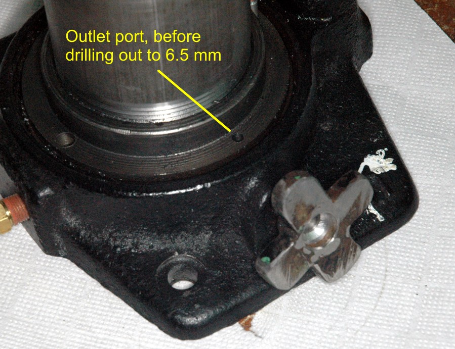
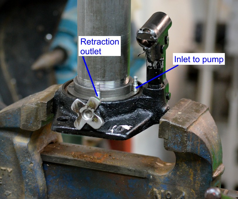
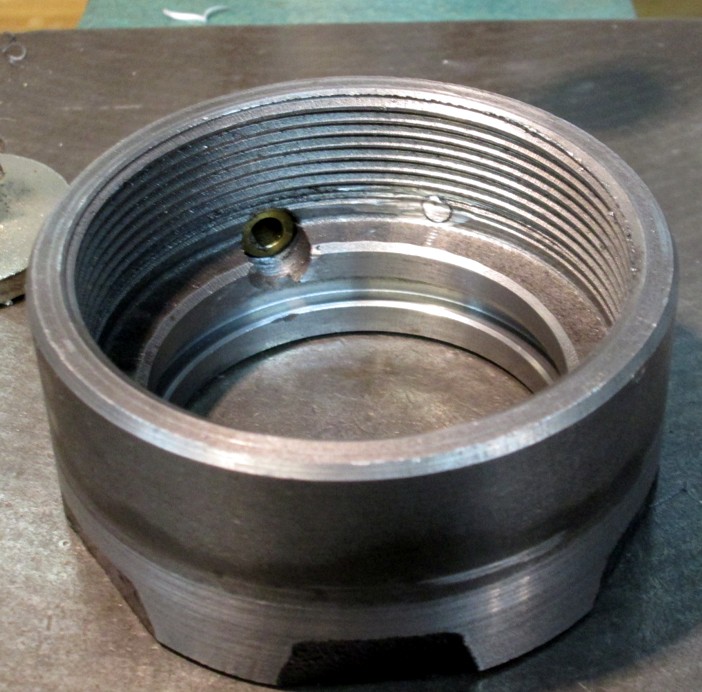
The planned new system entailed a minimum of extra work with the jack in pieces. Firstly, I needed to add a hollow barb to the outlet of the retraction valve, I had previously fitted a similar barb to the pump inlet, as described in my first post. The exit hole was too small so I drilled it out to 6.5 mm to a depth that didn’t run into the sealing O-ring nor the ball bearing used to seal the cylinder when the valve is closed.
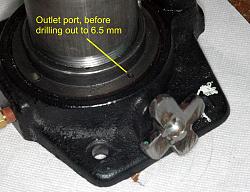
The outlet or retraction port, the oil exits through here when the ram is retracted. A hose connection barb is pressed into the port with an interference of around 0.03 mm to seal and hold it in place.
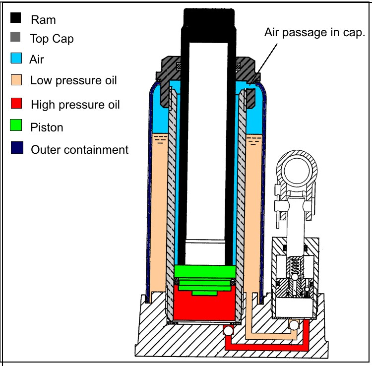
Let’s look at a comparison of the working end of the jack in three different configurations.
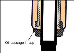
On the left is the normal rightwayup configuration with an air space above the low pressure oil. The centre shows my initial upsidedown version where there is no air in the jack and the original air passage serves as an oil passage as the ram is moved. It was because there is so much oil held back by the wiper seal in the cap that when the seal leaked it dropped so much oil. On the right is my current configuration. The outer cover is removed and the gap between the ram and cylinder has returned to being mainly air except for any leakage passed the piston seal. The air passage to prevent unwanted pressure build up still needs to vent and a hose is fitted down to the new reservoir tank.
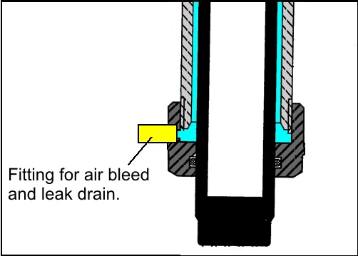
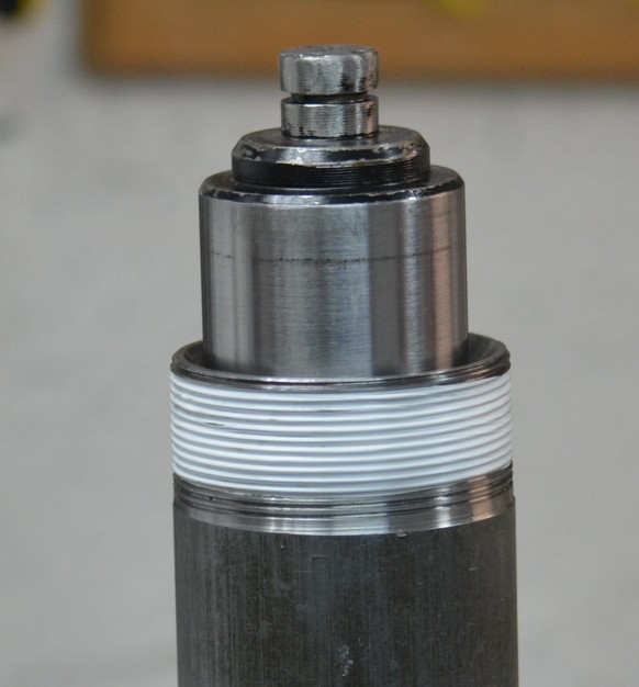
I wanted the drain passage to be as low as possible to minimize the amount of oil that could build up behind the ram wiper seal in the event that the main piston seal leaked. The existing passage drilled in the cap was higher than it could be so I blocked that hole off and drilled and tapped one a little lower down just on top of the sealing O-ring, for a small hose fitting.


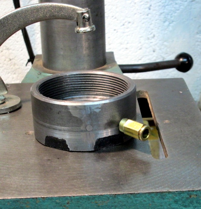
The original bleed hole can be seen blocked off with the new hole and fitting installed slightly lower down.
With the outer containment cylinder removed the top cap now has nothing solid to screw up against and will screw on until the thread gets tight. This does not usually result in a good seal and despite the fact that the drain hose location should totally avoid any leaked oil getting high enough to leak past the top of the cap, I wrapped the threads in sealing teflon tape. Unnecessary really, but it does no harm and the cap should be easier to remove if needed in the future.
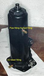
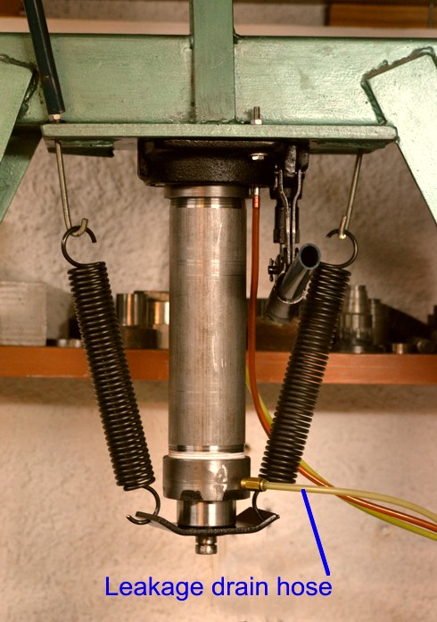
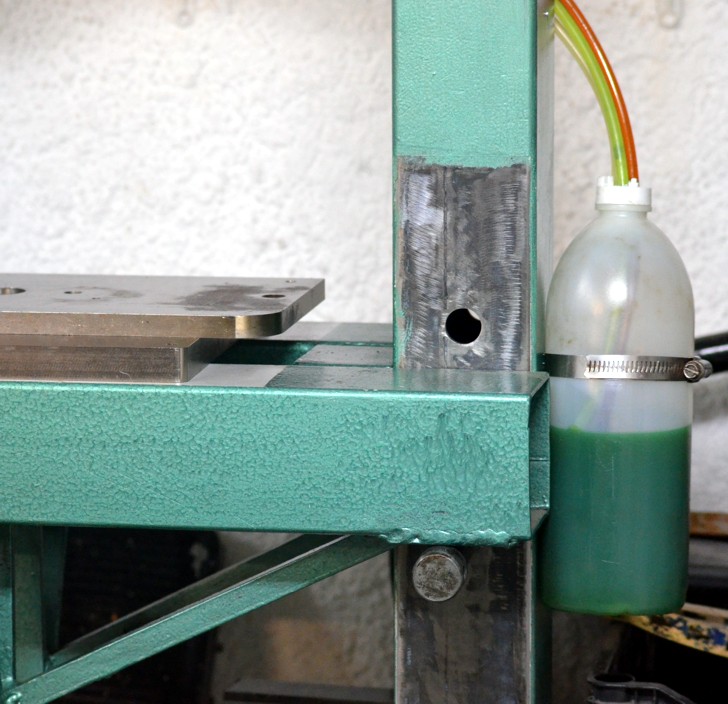
Here is the jack mounted to the press, showing the bleed/drain fitting and hose.
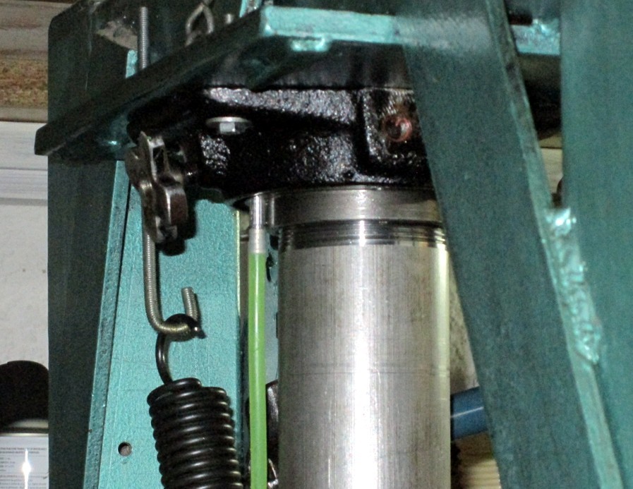
The rear of the mounted jack showing the oil return hose fitted to the new barb.
The new reservoir is mounted below the jack to allow the draining to work. The pump sucks oil up with no problem. Even if a major seal failure occurred in the jack it would be impossible to lose the reservoir contents.
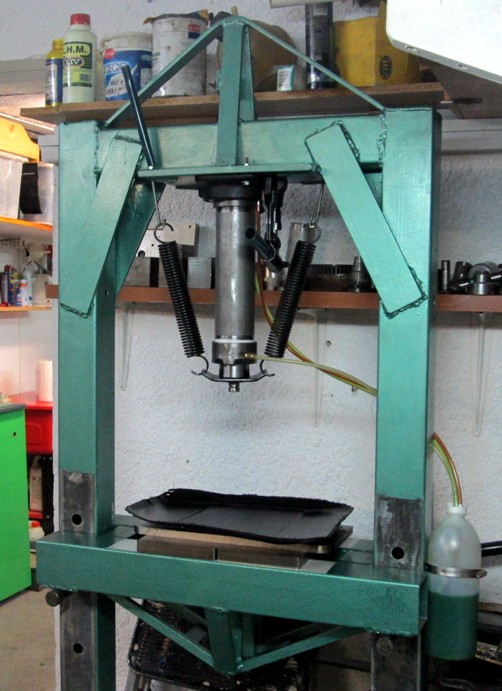
Here is the reassembled press, note the three tubes going to the reservoir, the red one is the feed to the pump inlet, the green one is the exhaust which carries oil expelled when the ram retracts and the clear one at the bottom is the air breather and drain for any leaked oil. It looks like a plumber’s nightmare but in reality it is quite simple and doesn’t require much work to convert a stock jack.
IT WORKS VERY WELL.
PS. My jack doesn't have a safety blow off valve. Jacks that do will need an extra drain hose unless they will never be used close to maximum load.


 Reply With Quote

Bookmarks