Free 186 More Best Homemade Tools eBook:  
Get 2,000+ tool plans, full site access, and more.

User Tag List

Page 1 of 4 1 2 3 4 LastLast
Results 1 to 10 of 32

Thread: Non-circular boring. (Linuxcnc fun)

  1. #1

    Join Date
    Jul 2019
    Posts
    33
    Thanks
    0
    Thanked 32 Times in 10 Posts

    Non-circular boring. (Linuxcnc fun)

    This is how I spend my weekends.. I am such a nerd..


    186 More Best Homemade Tools eBook

  2. The Following 3 Users Say Thank You to skunkworks For This Useful Post:

    Inner (Mar 10, 2020), Jon (Mar 31, 2020), tonyfoale (Apr 1, 2020)

  3. #2
    Supporting Member dagrizz's Avatar
    Join Date
    Nov 2019
    Posts
    22
    Thanks
    9
    Thanked 10 Times in 6 Posts
    Definitely an interesting use of a boring tool. Care to share the code for generating the toolpath?

    2000 Tool Plans

  4. #3

    Join Date
    Jul 2019
    Posts
    33
    Thanks
    0
    Thanked 32 Times in 10 Posts
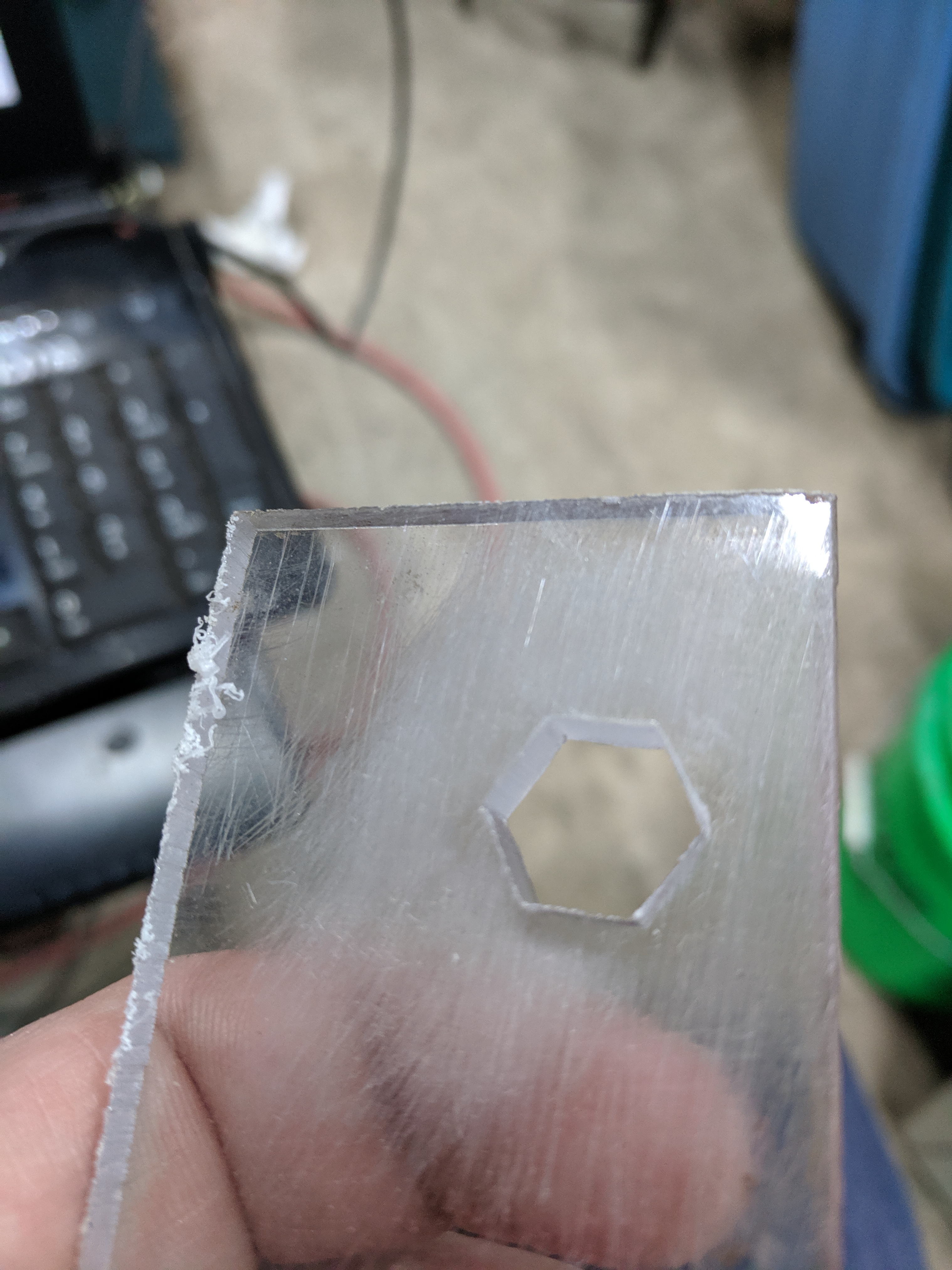
    First couple tries in plastic. (painfully slow - just testing) (and the hole size should be way closer to the inscribed polygon diameter...)


    Quote Originally Posted by dagrizz View Post
    Definitely an interesting use of a boring tool. Care to share the code for generating the toolpath?

    This is the hal component for linuxcnc... WIP use at your own risk.

    Code:
    //   This is a component for Linuxcnc HAL
    //   Copyright 2020 Sam Sokolik <samcoinc@gmail.com>
    //
    //   This program is free software; you can redistribute it and/or modify
    //   it under the terms of the GNU General Public License as published by
    //   the Free Software Foundation; either version 2 of the License, or
    //   (at your option) any later version.
    //
    //   This program is distributed in the hope that it will be useful,
    //   but WITHOUT ANY WARRANTY; without even the implied warranty of
    //   MERCHANTABILITY or FITNESS FOR A PARTICULAR PURPOSE.  See the
    //   GNU General Public License for more details.
    //
    //   You should have received a copy of the GNU General Public License
    //   along with this program; if not, write to the Free Software
    //   Foundation, Inc., 51 Franklin Street, Fifth Floor, Boston, MA 02110-1301 USA.
    component polygon "Create a spindle synced motion that carves a polygon using eoffset inputs.  Assumes positive rotation.";
     
    pin in bit enable;
    pin in unsigned numsides=3 "Number of sides in the polygon";
    pin in float inscribedradius=1 "inscribed radius of the polygon";
    pin in float cutterdiam "cutter diameter";
    pin in float eoffsetscale "scale that eoffset is set to.";
    pin in float toolang "angle difference between index and actual tool poition";
    pin in float spindlepos "Spindle position scaled to 1 per rev";
    pin out float spindlerad "Spindle postion in radians";
    pin out float polyradius "radious of the polygon at given spindle position";
    pin out float xoffset "x offset to send to offset componant";
    pin out float yoffset "y offset to send to the offset componant";
    pin out signed xeoffset "x eoffset output";
    pin out signed yeoffset "y eoffset output";
    pin out bit isindex "set index enable only once";
    pin io bit indexenable "hooked to index enable of encoder";
     
    function _;
    license "GPL";
    ;;
    #include  <rtapi_math.h>
    #define  PI 3.14159265358979323846
    float spinang;
    float scale;
    float spinangoffset;
     
        if (!enable) {
            xoffset=0;
            yoffset=0;
            xeoffset=0;
            yeoffset=0;
            isindex = false;
            return;
        }
     
    // only set index enable once
        if (enable && !isindex) {
        isindex = true;
        indexenable = true;
            return;
        }
     
    // wait for spindle index before actually enabling
        if (enable && isindex && indexenable){
            return;
        }
     
    //convert spinangoffset to ratio.. for adding to spindle pos - plus a couple rotations
    //so the spindle position isn't negative
    spinangoffset = (toolang/360)+2;
     
    //formual I found is for circumscribed - convert to inscribed - makes more sense.
    scale=inscribedradius/cos(PI/numsides);
     
    spinang = ((spindlepos + spinangoffset) - (int)(spindlepos + spinangoffset))*2*PI;
    polyradius = (cos(PI/numsides)/cos((fmod(spinang, (2*PI/numsides))-PI/numsides)))*scale-cutterdiam/2;
     
    //actual offsets applied - could be used for offset componant.
    xoffset = cos(spinang)*polyradius * -1;
    yoffset = sin(spinang)*polyradius;
     
    //counts for use with eoffset functionality
    xeoffset = xoffset / eoffsetscale;
    yeoffset = yoffset / eoffsetscale;
     
    spindlerad = spinang;
    Last edited by skunkworks; Mar 10, 2020 at 09:12 PM.

  5. #4

    Join Date
    Jul 2019
    Posts
    33
    Thanks
    0
    Thanked 32 Times in 10 Posts
    now in aluminum!!


  6. The Following 2 Users Say Thank You to skunkworks For This Useful Post:

    Karl_H (Mar 31, 2020), Tonyg (Mar 31, 2020)

  7. #5
    Supporting Member CharlesWaugh's Avatar
    Join Date
    May 2018
    Location
    Boring, OR
    Posts
    330
    Thanks
    57
    Thanked 309 Times in 117 Posts

    CharlesWaugh's Tools
    OK, that is COOL
    : - )
    Charles Waugh
    www.charleswaugh.com
    "Any tool is just a kit, to be modified as needed for the job at hand"

  8. #6
    Supporting Member Ralphxyz's Avatar
    Join Date
    Dec 2016
    Posts
    1,575
    Thanks
    2,487
    Thanked 280 Times in 229 Posts

    Ralphxyz's Tools
    Helps to have a CNC mill.

  9. #7

    Join Date
    Jul 2019
    Posts
    33
    Thanks
    0
    Thanked 32 Times in 10 Posts
    That is only part of it....

    Quote Originally Posted by Ralphxyz View Post
    Helps to have a CNC mill.

  10. #8
    Supporting Member tonyfoale's Avatar
    Join Date
    Nov 2016
    Location
    Spain
    Posts
    1,558
    Thanks
    686
    Thanked 2,643 Times in 708 Posts

    tonyfoale's Tools
    I have two questions;
    1. Is the cutting mainly done by the XY table movement and the tool rotation is principally to present the tool at the required rake angle to the line of movement at each location on the path?
    2. I am not familiar with Linux nor LinuxCNC, but I notice that you use a HAL file for the control. Is that because LinuxCNC does not use Gcode (I thought it did) or does a HAL file have advantages over Gcode?

    I have been thinking of making a rotary broach but this is a much better approach for general work because you do not need a new broach for each size and shape of hole. A small and large boring bar is all you need for any size and shape. Now I'll have to write some Gcode, although a search of the net might turn up a wheel already invented by another.
    Nice work BTW.

    PS. I just realised that I'll have to add a rotary encoder to my spindle before I can follow your example. I have been meaning to do that for a while now, this is just the motivation needed.

  11. #9

    Join Date
    Jul 2019
    Posts
    33
    Thanks
    0
    Thanked 32 Times in 10 Posts
    Quote Originally Posted by tonyfoale View Post
    I have two questions;
    1. Is the cutting mainly done by the XY table movement and the tool rotation is principally to present the tool at the required rake angle to the line of movement at each location on the path?
    Kind of - it would be impossible to keep the tool at the correct rake angle unless the tool had no thickness. Even then. The code just keeps the tool perpendicular to the center of the polygon. It works surprisingly well it seems (even if the tool isn't exactly at the right angle compared to the material.) So - half the time it is negative-ish and half the time it is positve-ish

    Quote Originally Posted by tonyfoale View Post
    2. I am not familiar with Linux nor LinuxCNC, but I notice that you use a HAL file for the control. Is that because LinuxCNC does not use Gcode (I thought it did) or does a HAL file have advantages over Gcode?
    The Hal component is what does the realtime stuff to do the motion. This can be controlled by gcode. The code is run 1000 times a second and reads the spindle position and calculates where x/y need to be. There are a bunch of parameters that you set (number of sides, cutter diameter, polygon radius and so on) I will get my gcode example to show you. The next step would be to do what is called a gcode re-map. So you could make it more user friendly. (one line of gcode maybe sets and enables the component)

    Quote Originally Posted by tonyfoale View Post
    I have been thinking of making a rotary broach but this is a much better approach for general work because you do not need a new broach for each size and shape of hole. A small and large boring bar is all you need for any size and shape. Now I'll have to write some Gcode, although a search of the net might turn up a wheel already invented by another.
    Nice work BTW.

    PS. I just realised that I'll have to add a rotary encoder to my spindle before I can follow your example. I have been meaning to do that for a while now, this is just the motivation needed.
    thanks!

  12. #10
    Supporting Member tonyfoale's Avatar
    Join Date
    Nov 2016
    Location
    Spain
    Posts
    1,558
    Thanks
    686
    Thanked 2,643 Times in 708 Posts

    tonyfoale's Tools
    Quote Originally Posted by skunkworks View Post
    The code is run 1000 times a second and reads the spindle position and calculates where x/y need to be. There are a bunch of parameters that you set (number of sides, cutter diameter, polygon radius and so on)
    Yes I realised what was going on there, I did not know the timing of course. You cutting feeds and speeds are quite low, is that because of limitations of your mill or the software or was it to make a watchable video?

    Quote Originally Posted by skunkworks View Post
    I will get my gcode example to show you. The next step would be to do what is called a gcode re-map. So you could make it more user friendly. (one line of gcode maybe sets and enables the component)
    That would be great. It would save reinventing that wheel.

    Getting back to the HAL file. Am I right it assuming that is what drives LinuxCNC and you use a Gcode to HAL converter to be able to use Gcode from a CAM programme or hand written.

Thread Information

Users Browsing this Thread

There are currently 1 users browsing this thread. (0 members and 1 guests)

Bookmarks

Posting Permissions

  • You may not post new threads
  • You may not post replies
  • You may not post attachments
  • You may not edit your posts
  •