Free 186 More Best Homemade Tools eBook:  
Get 2,000+ tool plans, full site access, and more.

User Tag List

Page 1 of 2 1 2 LastLast
Results 1 to 10 of 13

Thread: overhead bridge crane

  1. #1
    Supporting Member Frank S's Avatar
    Join Date
    Aug 2015
    Location
    Peacock TX
    Posts
    11,227
    Thanks
    1,986
    Thanked 8,789 Times in 4,207 Posts

    Frank S's Tools

    overhead bridge crane

    Every shop needs lifting devices I have a few jib cranes a couple chain hoists hanging from the ceiling, A large unwieldly forklift that is so big I can't turn it around inside the shop, But, what I really needed is an overhead bridge crane to service one of my bays. The way I built the trusses I can add more of them later.
    Here is how I came up with a way to install one.
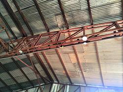
    Many people are familiar with the way some roller-coaster tracks are mad out of pipe All they need is to support the rails more closely than a beam rail style the wheels are profiled to fit the OD of the pipe. My trusses as strong enough to serve as the supports so instead of needing beams for the crane to hang from or ride on top of square rails I used 2 7/8" oilfield pipes as the rails.
    overhead bridge crane-img_20230722_131602oc.jpg
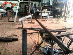
    The pipe rails are welded to the top of the bottom truss member every 2 feet Via 1/2By 3 flat bar with gusset support on the pipe to prevent rollover stresses
    overhead bridge crane-img_20230725_121413oc.jpg
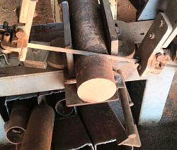
    The beginning of the rollers is a length of 3 1/2" round bar
    overhead bridge crane-img_20230727_100131oc.jpg
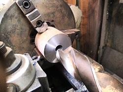
    A 2" hole was bored through it
    overhead bridge crane-img_20230727_102959oc.jpg
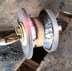
    Then flanges welded to it to allow for the profile machining of the roller
    overhead bridge crane-img_20230727_140033oc.jpg
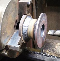
    Machining the bearing locations for 6306 bearings 30 Bore x72 OD x19 mm wide
    overhead bridge crane-img_20230727_144100oc.jpg
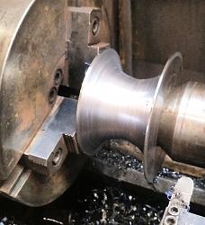
    Machining the profile
    overhead bridge crane-img_20230727_171834oc.jpg
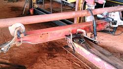
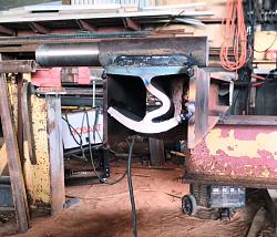
    I had a pair of cross rails from an old Globe 8000lb 4 post lift that I used for the end trucks and bracing of the bridge
    overhead bridge crane-img_20230802_090028oc.jpg
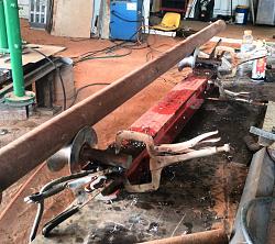
    View of 1 end truck assembly using a length of pipe for aligning
    overhead bridge crane-img_20230802_090051oc.jpg
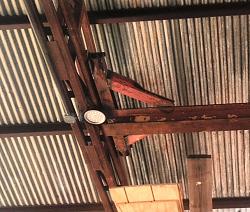
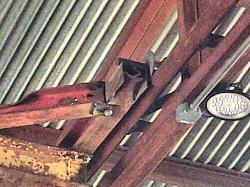
    View of the end of the end truck with spindle welded in place note the compressed state of the end of the cross rail beam I used this proved to be beneficial in my design.
    overhead bridge crane-img_20230802_141940oc.jpg
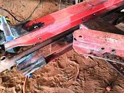
    Aligning the spindles for welding
    overhead bridge crane-img_20230802_154619oc.jpg
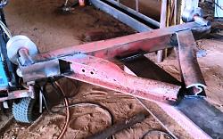
    One end is bolted to the top of the bridge while the other end truck is welded this was done so the bridge could be installed. Note how the compressed beam pieces cut off from the ends of the cross rails worked out for bracing
    overhead bridge crane-img_20230803_144845oc.jpg
    overhead bridge crane-img_20230803_162013oc.jpg
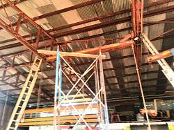
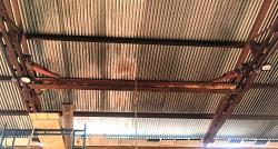
    Hanging the bridge
    overhead bridge crane-img_20230807_085442oc.jpg
    overhead bridge crane-img_20230817_134951oc.jpg
    overhead bridge crane-img_20230817_135049oc.jpg
    Only thing left is to come up with a hoist for it then testing.
    Truss calculations show the trusses can support a 10k load at the center of the 68ft span, the 14 ft bridge is good for 3 tons center of span but I am only looing to install a 1-ton hoist,
    overhead bridge crane-img_20230817_135000oc.jpg
    Click image for larger version. 

Name:	IMG_20230807_085442oc.jpg 
Views:	307 
Size:	366.7 KB 
ID:	46072

    Click image for larger version. 

Name:	IMG_20230802_154619oc.jpg 
Views:	270 
Size:	378.3 KB 
ID:	46069
    Click image for larger version. 

Name:	IMG_20230802_141940oc.jpg 
Views:	322 
Size:	338.5 KB 
ID:	46068
    Click image for larger version. 

Name:	IMG_20230802_090028oc.jpg 
Views:	287 
Size:	352.4 KB 
ID:	46066

    186 More Best Homemade Tools eBook
    Never try to tell me it can't be done
    When I have to paint I use KBS products

  2. The Following 17 Users Say Thank You to Frank S For This Useful Post:

    baja (Aug 22, 2023), Christophe Mineau (Aug 22, 2023), Inner (Aug 25, 2023), Jon (Aug 25, 2023), KustomsbyKent (Aug 22, 2023), Metallurg33 (Aug 25, 2023), metric_taper (Aug 21, 2023), mr mikey (Aug 25, 2023), mwmkravchenko (Aug 21, 2023), nova_robotics (Aug 21, 2023), papa bill2 (Aug 25, 2023), PaulsGarageProjects (Aug 23, 2023), Philip Davies (Aug 25, 2023), Ralphxyz (Aug 25, 2023), Scotty1 (Aug 20, 2023), sossol (Aug 21, 2023), Toolmaker51 (Aug 25, 2023)

  3. #2
    Content Editor
    Supporting Member
    DIYer's Avatar
    Join Date
    Aug 2013
    Posts
    3,056
    Thanks
    773
    Thanked 1,853 Times in 1,654 Posts


    Thanks Frank S! We've added your Overhead Bridge Crane to our Cranes category,
    as well as to your builder page: Frank S's Homemade Tools. Your receipt:


    2000 Tool Plans

  4. #3
    Supporting Member mwmkravchenko's Avatar
    Join Date
    Nov 2017
    Location
    Perth Ontario Canada
    Posts
    1,013
    Thanks
    5,097
    Thanked 377 Times in 266 Posts
    That was some press that squashed that I-beam originally. Like your Rollers Frank. Wishing I had a welder with enough giddyup to make such a weld. Did you form them by hand on the lathe?

    Mark

  5. #4
    Supporting Member Frank S's Avatar
    Join Date
    Aug 2015
    Location
    Peacock TX
    Posts
    11,227
    Thanks
    1,986
    Thanked 8,789 Times in 4,207 Posts

    Frank S's Tools
    Quote Originally Posted by mwmkravchenko View Post
    That was some press that squashed that I-beam originally. Like your Rollers Frank. Wishing I had a welder with enough giddyup to make such a weld. Did you form them by hand on the lathe?

    Mark
    Hand cut the radius profile, never got around to making a radius or ball profiling attachment.
    Never try to tell me it can't be done
    When I have to paint I use KBS products

  6. The Following User Says Thank You to Frank S For This Useful Post:

    mwmkravchenko (Aug 21, 2023)

  7. #5
    Supporting Member Christophe Mineau's Avatar
    Join Date
    Jul 2014
    Location
    France, Brittany !
    Posts
    913
    Thanks
    826
    Thanked 1,691 Times in 481 Posts

    Christophe Mineau's Tools
    That's impressive work Franck, I've always been impressed by how things seem to be so easy to you when building such big things.
    How did you manage to hang this big thing that high under your roof?
    Did you do that alone ?
    How much time did you take to complete this project ?
    Cheers !
    Christophe
    ________________________________________________________________
    Visit my Website : http://www.labellenote.fr/
    Facebook : La Belle Note
    All my personal works, unless explicitly specified, are released under
    Creative Commons BY-NC-SA license.

  8. #6
    Supporting Member Frank S's Avatar
    Join Date
    Aug 2015
    Location
    Peacock TX
    Posts
    11,227
    Thanks
    1,986
    Thanked 8,789 Times in 4,207 Posts

    Frank S's Tools
    Quote Originally Posted by Christophe Mineau View Post
    That's impressive work Franck, I've always been impressed by how things seem to be so easy to you when building such big things.
    How did you manage to hang this big thing that high under your roof?
    Did you do that alone ?
    How much time did you take to complete this project ?
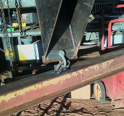
    I used my homemade 12" bucket on my backhoe with a hole cut in it near the cutting edge. I have a cargo D ring welded in the center of the top of the beam with a clevis I attached it to the bucket Set the outriggers of the backhoe to lift it as high as possible and the loader bucket down just enough to stabilize it Raised the beam as high as the backhoe could go then sitting in the backhoe with the end of a rope I had hooked on 1 end I rotated the beam enough so the rollers would align with the rails then curled the bucked in until the beam was resting in place and the shackles were freed disconnected and removed the backhoe. About half an hour to hang it but 2 days to build it
    I hung the pipe rails much the same way with the back hoe then up the ladders to clamp them in place A string line stretched end for end used 12" C clamp to pull the pipe rails straight 1 mounting tab at a time A hose clamp around the pipes to hold 1 end of a tape measure using a ladder at both pipes a lot of climbing up and down until I had the ends parallel used maybe 6 clamps on each pipe . Welded 1 end of both of them then using the F150 with scaffolding I could work 3 mounting tabs then move to the next About 3 days to get the rails made and welded in place I wouldn't know what to do with a helper except for have them fetch things for me. Would have come in handy though when measuring the distance between the beams LOL.
    overhead bridge crane-img_20230806_195206oc.jpg
    Never try to tell me it can't be done
    When I have to paint I use KBS products

  9. The Following 5 Users Say Thank You to Frank S For This Useful Post:

    Christophe Mineau (Aug 23, 2023), Jon (Aug 24, 2023), mwmkravchenko (Aug 22, 2023), Scotty1 (Aug 22, 2023), Toolmaker51 (Aug 25, 2023)

  10. #7
    charles scozzari's Avatar
    Join Date
    May 2016
    Location
    Staten Island NY
    Posts
    34
    Thanks
    103
    Thanked 45 Times in 13 Posts

    charles scozzari's Tools

    overhead crane

    Quote Originally Posted by Frank S View Post
    Every shop needs lifting devices I have a few jib cranes a couple chain hoists hanging from the ceiling, A large unwieldly forklift that is so big I can't turn it around inside the shop, But, what I really needed is an overhead bridge crane to service one of my bays. The way I built the trusses I can add more of them later.
    Here is how I came up with a way to install one.
    Many people are familiar with the way some roller-coaster tracks are mad out of pipe All they need is to support the rails more closely than a beam rail style the wheels are profiled to fit the OD of the pipe. My trusses as strong enough to serve as the supports so instead of needing beams for the crane to hang from or ride on top of square rails I used 2 7/8" oilfield pipes as the rails.
    Click image for larger version. 

Name:	IMG_20230722_131602oc.jpg 
Views:	254 
Size:	354.2 KB 
ID:	46059
    The pipe rails are welded to the top of the bottom truss member every 2 feet Via 1/2By 3 flat bar with gusset support on the pipe to prevent rollover stresses
    Click image for larger version. 

Name:	IMG_20230725_121413oc.jpg 
Views:	257 
Size:	398.4 KB 
ID:	46060
    The beginning of the rollers is a length of 3 1/2" round bar
    Click image for larger version. 

Name:	IMG_20230727_100131oc.jpg 
Views:	228 
Size:	290.7 KB 
ID:	46061
    A 2" hole was bored through it
    Click image for larger version. 

Name:	IMG_20230727_102959oc.jpg 
Views:	164 
Size:	294.5 KB 
ID:	46062
    Then flanges welded to it to allow for the profile machining of the roller
    Click image for larger version. 

Name:	IMG_20230727_140033oc.jpg 
Views:	180 
Size:	299.8 KB 
ID:	46063
    Machining the bearing locations for 6306 bearings 30 Bore x72 OD x19 mm wide
    Click image for larger version. 

Name:	IMG_20230727_144100oc.jpg 
Views:	169 
Size:	305.1 KB 
ID:	46064
    Machining the profile
    Click image for larger version. 

Name:	IMG_20230727_171834oc.jpg 
Views:	157 
Size:	466.0 KB 
ID:	46065
    I had a pair of cross rails from an old Globe 8000lb 4 post lift that I used for the end trucks and bracing of the bridge
    Click image for larger version. 

Name:	IMG_20230802_090028oc.jpg 
Views:	287 
Size:	352.4 KB 
ID:	46066
    View of 1 end truck assembly using a length of pipe for aligning
    Click image for larger version. 

Name:	IMG_20230802_090051oc.jpg 
Views:	204 
Size:	289.1 KB 
ID:	46067
    View of the end of the end truck with spindle welded in place note the compressed state of the end of the cross rail beam I used this proved to be beneficial in my design.
    Click image for larger version. 

Name:	IMG_20230802_141940oc.jpg 
Views:	322 
Size:	338.5 KB 
ID:	46068
    Aligning the spindles for welding
    Click image for larger version. 

Name:	IMG_20230802_154619oc.jpg 
Views:	270 
Size:	378.3 KB 
ID:	46069
    One end is bolted to the top of the bridge while the other end truck is welded this was done so the bridge could be installed. Note how the compressed beam pieces cut off from the ends of the cross rails worked out for bracing
    Click image for larger version. 

Name:	IMG_20230803_144845oc.jpg 
Views:	169 
Size:	405.0 KB 
ID:	46070
    Click image for larger version. 

Name:	IMG_20230803_162013oc.jpg 
Views:	163 
Size:	262.6 KB 
ID:	46071
    Hanging the bridge
    Click image for larger version. 

Name:	IMG_20230807_085442oc.jpg 
Views:	307 
Size:	366.7 KB 
ID:	46072
    Click image for larger version. 

Name:	IMG_20230817_134951oc.jpg 
Views:	187 
Size:	288.5 KB 
ID:	46073
    Click image for larger version. 

Name:	IMG_20230817_135049oc.jpg 
Views:	171 
Size:	268.8 KB 
ID:	46074
    Only thing left is to come up with a hoist for it then testing.
    Truss calculations show the trusses can support a 10k load at the center of the 68ft span, the 14 ft bridge is good for 3 tons center of span but I am only looing to install a 1-ton hoist,
    Click image for larger version. 

Name:	IMG_20230817_135000oc.jpg 
Views:	164 
Size:	277.4 KB 
ID:	46075
    Click image for larger version. 

Name:	IMG_20230807_085442oc.jpg 
Views:	307 
Size:	366.7 KB 
ID:	46072

    Click image for larger version. 

Name:	IMG_20230802_154619oc.jpg 
Views:	270 
Size:	378.3 KB 
ID:	46069
    Click image for larger version. 

Name:	IMG_20230802_141940oc.jpg 
Views:	322 
Size:	338.5 KB 
ID:	46068
    Click image for larger version. 

Name:	IMG_20230802_090028oc.jpg 
Views:	287 
Size:	352.4 KB 
ID:	46066
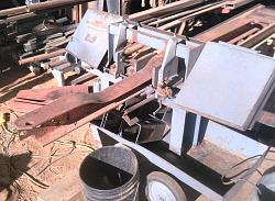
    Love what you've made. Will be well worth the effort. I noticed your band saw, did you make it.?

  11. The Following User Says Thank You to charles scozzari For This Useful Post:

    Frank S (Aug 25, 2023)

  12. #8
    Dry Creek Smithing
    Supporting Member

    Join Date
    Feb 2018
    Location
    CA, USA.
    Posts
    76
    Thanks
    3
    Thanked 20 Times in 17 Posts
    Frank,
    I love your overhead lift project. Years ago I worked in a truck shop We had two of these type of beasts in the shop. Between the two they covered the whole shop floor. We could could disassemble a truck in now time. Breaking it down to just bare frame rails in a matter of a few hours by lifting off and away the large components. Weight and mass seemed a non-issue with those two pieces of equipment. We were spoiled! You are going to love your new addition to your shop. Thanks for the great pictures of the process. Not an easy task while building. I would get so focused on the task that I'd forget to take shots of each step.
    Wonderful work and great secondary use of material as well. Many of my friend don't get my "Stuff". They call it Junk, trash, scrap!

    I've seen it posted on this site some where maybe your thread...
    "It's not junk! It is inventory for future projects!".
    Well said!!!

    Doug D.C. Smithing

  13. The Following User Says Thank You to Dry Creek Smithing For This Useful Post:

    Frank S (Aug 25, 2023)

  14. #9
    Supporting Member Frank S's Avatar
    Join Date
    Aug 2015
    Location
    Peacock TX
    Posts
    11,227
    Thanks
    1,986
    Thanked 8,789 Times in 4,207 Posts

    Frank S's Tools
    [QUOTE=charles scozzari;227750]Love what you've made. Will be well worth the effort. I noticed your band saw, did you make it.?[/QUOTE
    Thanmks; No the bansdaw is a W.E.Wells &Sons
    Never try to tell me it can't be done
    When I have to paint I use KBS products

  15. #10
    Supporting Member Philip Davies's Avatar
    Join Date
    Dec 2015
    Location
    Reading, Berks, UK
    Posts
    876
    Thanks
    1,194
    Thanked 1,022 Times in 343 Posts

    Philip Davies's Tools
    As it happens, Frank, I have just made up a workshop crane, for my 8’ x 6’ shed! I have a question for forum members. The new block & tackle is just to raise my compound table from its shelf onto the bench drill. The line supplied is 3-ply nylon and I don’t see how it can be used, since it twists, of course. Can I expect to remedy the twist by stretching the line against the twist, or have I sufficient grounds for a refund, doyouthink?overhead bridge crane-image.jpg

Thread Information

Users Browsing this Thread

There are currently 1 users browsing this thread. (0 members and 1 guests)

Bookmarks

Posting Permissions

  • You may not post new threads
  • You may not post replies
  • You may not post attachments
  • You may not edit your posts
  •