 LinkBack URL
 About LinkBacks
I have the same problem type lathe, you have done a Excellent job with the conversion ,I suppose you would not nip over and do mine,Great Job.


I have the same problem type lathe, you have done a Excellent job with the conversion ,I suppose you would not nip over and do mine,Great Job.


Rofl: "Nip over...". He's either nearby or other half of the planet? He'd be certainly be a terrific visitor!Originally Posted by sacco1

I'm jealous regarding Bayonet mount system; completely unfamiliar to me. Still shot of vid told me "aaha, converting to short taper A1 or A2."
Nope, not even close. we share no pity for threaded spindles. Not even complimentary on indexers etc. I've had a milling cutter impart enough leverage causing a chuck loosening, while climbing a transverse slot.
The bayonet carries benefits akin A1, A2, D, and L. The biggest to me, is split but accomplished simultaneously, positive drive and positive orientation. A's, Bayonet and L get that built-in with the drive boss [A's and Bayonet] or key [L's]. D requires a step you undertake personally. The cam pins impart positive drive, but there is no feature returning to same bores they are initially set for. Yet I remain D-mount fan in lathes they are appropriate, which get pretty big.
Mark the chuck plate and spindle, a paint mark is sufficient. A chuck will take a stamp, most spindles hardened beyond range a stamp can penetrate. I feel assured when each cam is marked as well, indicating engagement.
Larger machines seem to depend on retention bolts of "A", where operating the spanner for "L", or Tee handle for "D" is pure gymnastics. Same machines rarely if ever have the chuck removed, as faceplate and jaws are combined.
But that bayonet!
https://www.smalltools.com/lathe-spi...ication-chart/
It's missing from this US version chart. It may be more common for European users.
Last edited by Toolmaker51; Feb 15, 2021 at 08:17 PM.
Sincerely,
Toolmaker51
...we'll learn more by wandering than searching...


[QUOTE=Toolmaker51;
I'm jealous regarding Bayonet mount system; completely unfamiliar to me. ................
It's missing from this US version chart. It may be more common for European users.[/QUOTE]
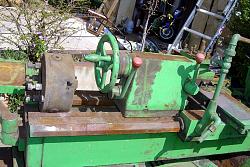
I think that it was European. The old lathe that I had with it on was of Spanish manufacture. I have seen a reference that they were fitted up until 1975. I that the A is the common fitting for the cheaper end and D for the less cheap.
I got that old lathe for the price of shipping. It looked to be very rusty but when I started cleaning it I realised that it was not the lathe that was rusty, it was the grinding grit that it was covered in. Apparently it had been stored where iron casting fettling was done. Within a week or so of getting it running I got a three year job offer, out of the blue, at Segway in the US. I bought my current lathe whilst in the US and so when I returned to Spain I scrapped the old lathe because the ways had a big wear dip right where it would be most used. It would have been a great lathe except for the wear, it was heavy and very rigid.
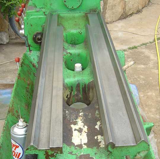
Click thumbnails for full size
Get an eyeful of those ways, NO scrimping there!
Later years then US heavy iron, Italy, Spain, Britain, areas around Poland, Czechoslovakia, likely Russia too, had no hesitation building heavy patterned machine castings. I'm sure the iron was of good specification like Meehanite, chilled, seasoned, induction hardened as measures of competition.
At same time German and Swiss offerings had thinner sections but far more webbing. I'm thinking those were chasing foreign markets [shipping], the heavy stuff more domestic.
Despite gargantuan appearance, those of Italian and central European makers operated in a very civil but positive manner. Had examined British, French and Spanish too, apparently not so many sold, never had one in front of me on a shop floor, save one HES lathe. That had wonderful collection of features, for certain.
Sincerely,
Toolmaker51
...we'll learn more by wandering than searching...
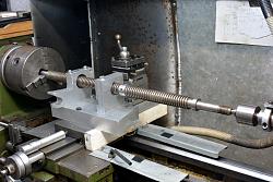
My old Spanish lathe did not have hardened ways hence the wear problem. There are times when I wish that I still had that machine for heavy work despite the wear. Did you notice the interesting feature of the ways? The tailstock had the normal - one flat/one pyramid - arrangement but the saddle had two pyramids.
I kept a lot of things when I scrapped that lathe and many have been put to good use. Several featured in my past posts.
The motor and gearbox were kept, of course. The motor was used to power my shock dyno; Shock dyno (or Shock absorber dynamometer)
The face plate and chuck back plate are used in this chuck mounting post.
Mounted on a square steel plate the chuck is used on the mill as a vice for round things.
I kept the cross slide and compound rest which was used in my brake drum grinder; Grinding machine for drum brakes.
The cylinder from the tailstock was the basis of my cylindrical square; Cylindrical square from a lathe tailstock.
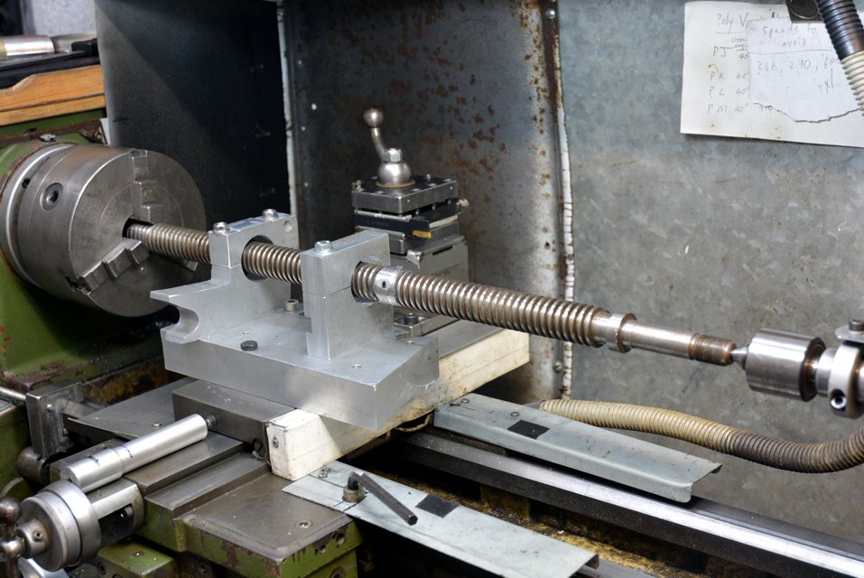
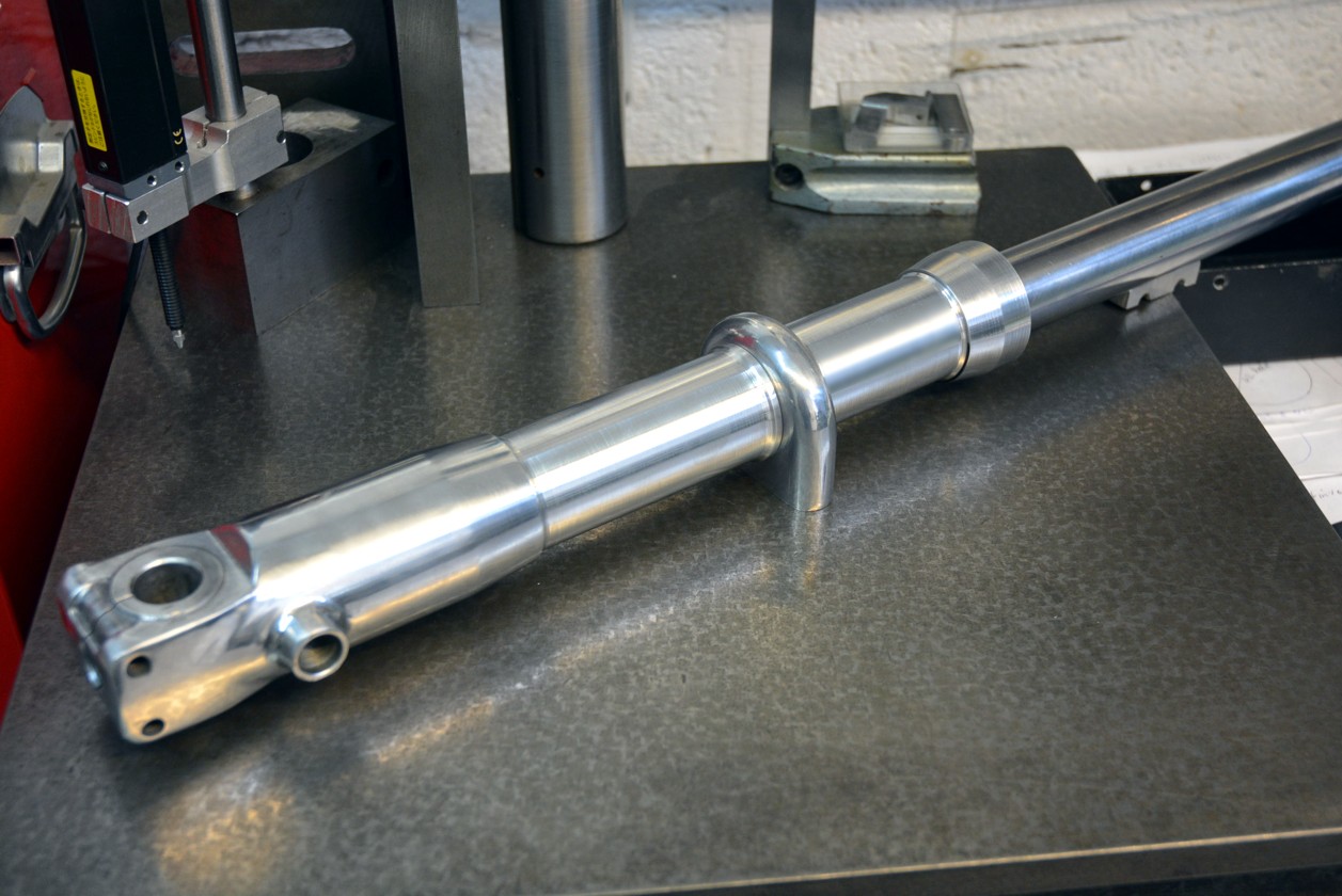
The lead screw was used to make the boring bar for a line boring setup that I used to make front forks.
Reusing madness.
Toolmaker51 (Feb 16, 2021)

Some great links but an important one is missing! I'm very interested in seeing your line boring setup. A write up can be tedious and time consuming, so I am not making that request, but maybe a couple of pics for the curious!
I have been thinking about the drive mechanism for such a machine but have made no progress. Visions of an Arduino/stepper/Mach III machine have languished as being too complicated for such a simple machine and flown off into the ether! I am now considering a Power Table feed accessory as a possible way to drive a lead screw. I would be interested in your thoughts.
OK, but just for the curious.
Click for full size.
The end result was making some 1960/70s replica front forks.
It depends on what you want to do with it. If you want uncoordinated axis moves then the unit that you mention would be fine. If you want to coordinate the moves on different axis then steppers would be the easiest solution.
There are currently 1 users browsing this thread. (0 members and 1 guests)
 Posting Permissions


 Reply With Quote
Bookmarks