
 LinkBack URL
 About LinkBacks


A shock dyno is a measuring tool for analysing the dynamic characteristics of the the damper part of a vehicle shock absorber. Over the period of their existence there have been several basic types used. The main types in chronological order being;
1. Mechanical
2. Hydraulic
3. Electric
Hydraulic and electric are typically hi-tech and very expensive, controlled by computer they can driven to provide different wave shape displacements and can even be fed with real road data to simulate real life loading on the shock.
Mechanical versions are the traditional and most numerous. A crank mechanism is used to convert rotary motion from an electric motor to linear motion to drive the shock. Modern machines use a VFD (variable frequency drive) to alter stroke velocity, and the crank radius is usually adjustable (either in steps or continuously) to alter the maximum displacement.
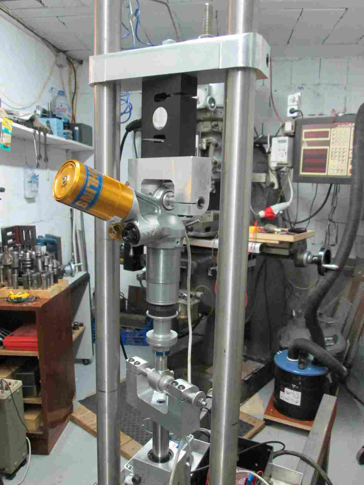
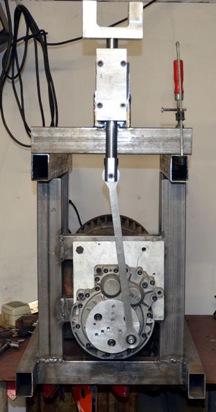
My need is to develop rear shocks and front forks for classic racing motorcycles and my budget does not run to an hydraulic or electric device so I decided to build my own take on the mechanical type. The following shows the completed tool with an Ohlins shock mounted.
Click thumbnails for full size.
Some machines use the crank to drive a Scotch Yoke to give sinusoidal stroke motion, others use a long conrod relative to stroke length to get a close approximation to a sinusoidal motion, the latter is the type that I decided to build because I see no special benefit in a true sinusoidal motion as long as the displacement is measured against time throughout the stroke. The other parameter that needs to be measured is the force exerted by the shock in response to the applied motion.
The following details the construction phase.

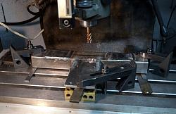
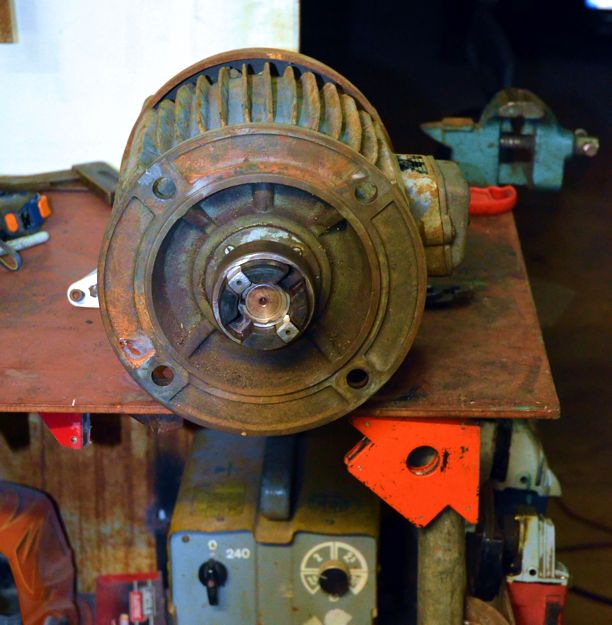
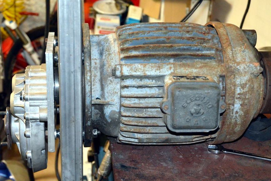
On the left is a 5 hp 3 ph motor which I kept from an old lathe which I had earmarked to power the machine. It was a flange mounting motor, I'd have preferred a base mounted type for ease of fitting. The start of the motor mounting is shown on the right being setup for making the holes for the mounting bosses.
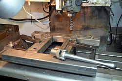
Preparing holes for the mounting bosses and then machining the bosses level.

Attaching the motor mounting sub-frame to the base frame.

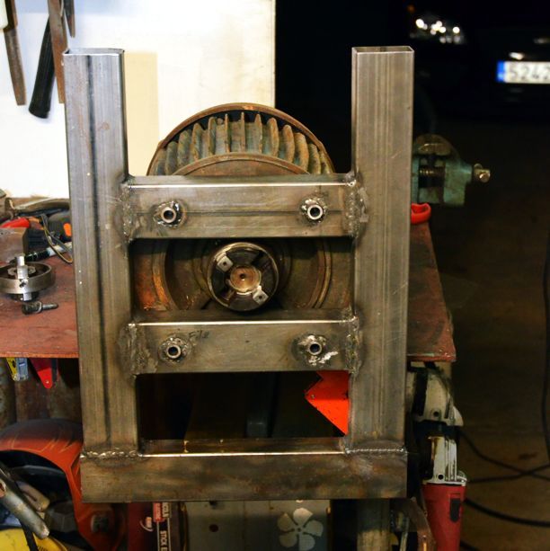
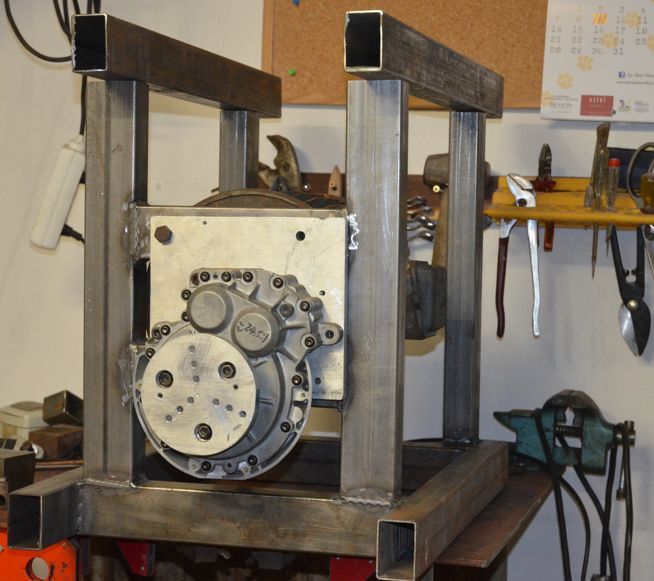
Here we have the motor mounting frame welded to the base, and also the mounting plate for a reduction gearbox.
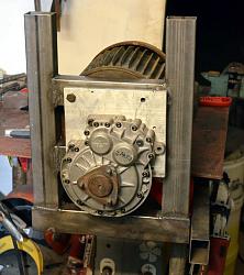
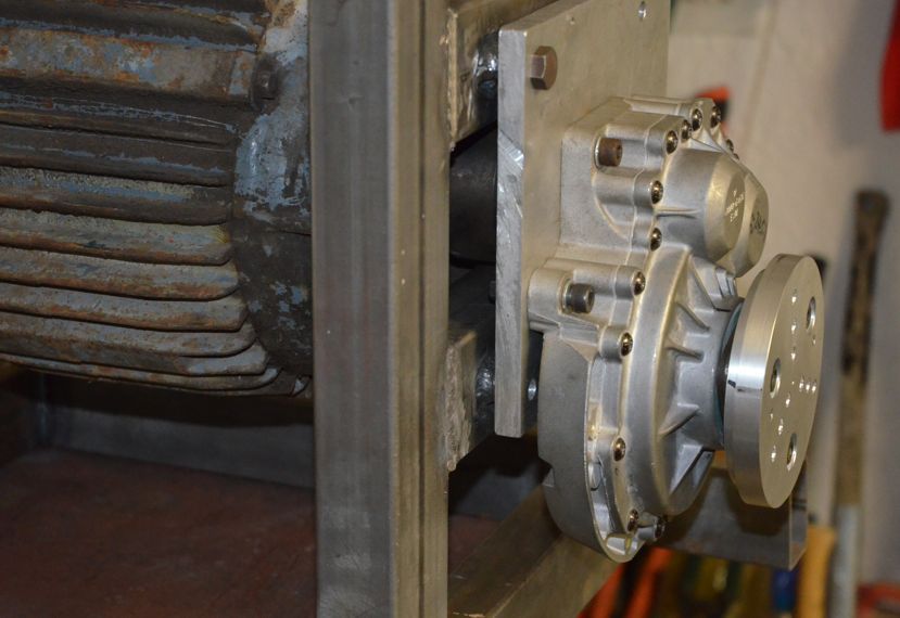
Showing both motor and 25:1 reduction gearbox mounted to the part completed frame.
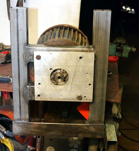
A couple of views showing the crank plate fitted to the gearbox output shaft. The tapped holes allow different maximum strokes of the shock.

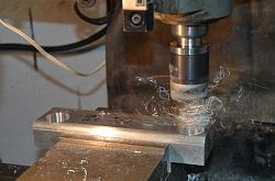
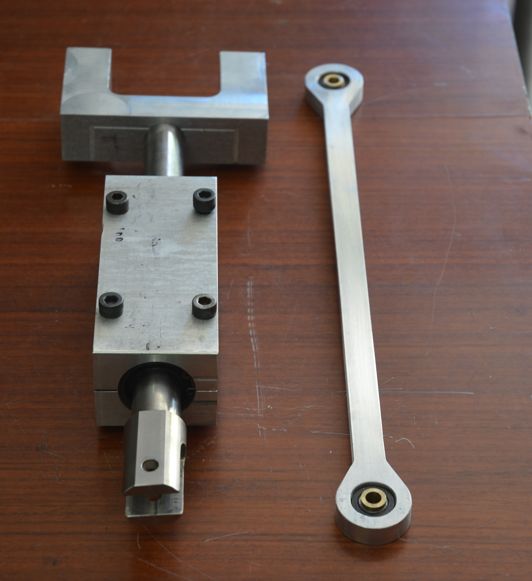
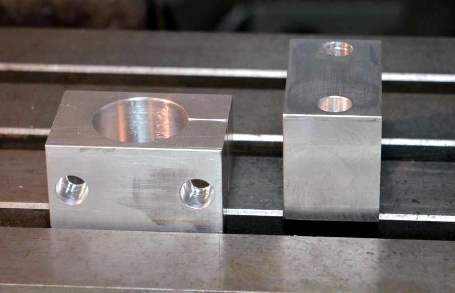
On the left is the slider block and conrod. I had some 1" ID linear ball races so I got a length of 1" Thompson shaft and made an aluminium housings for the bearings. The shaft moves very smoothly with a high degree of rigidity. The yoke at the top is for mounting a shock or fork slider. The second photo shows a trial mockup of the assembly.
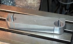
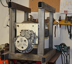
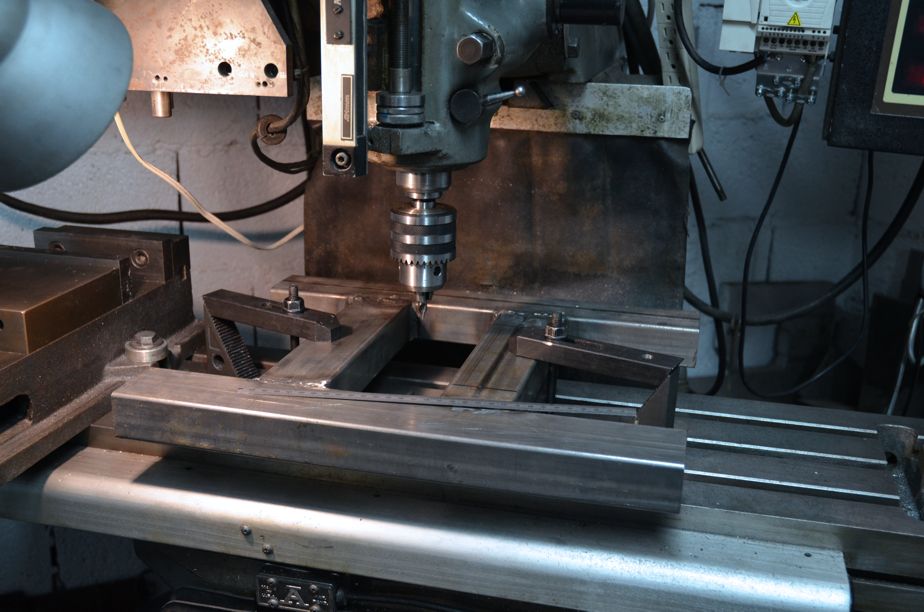
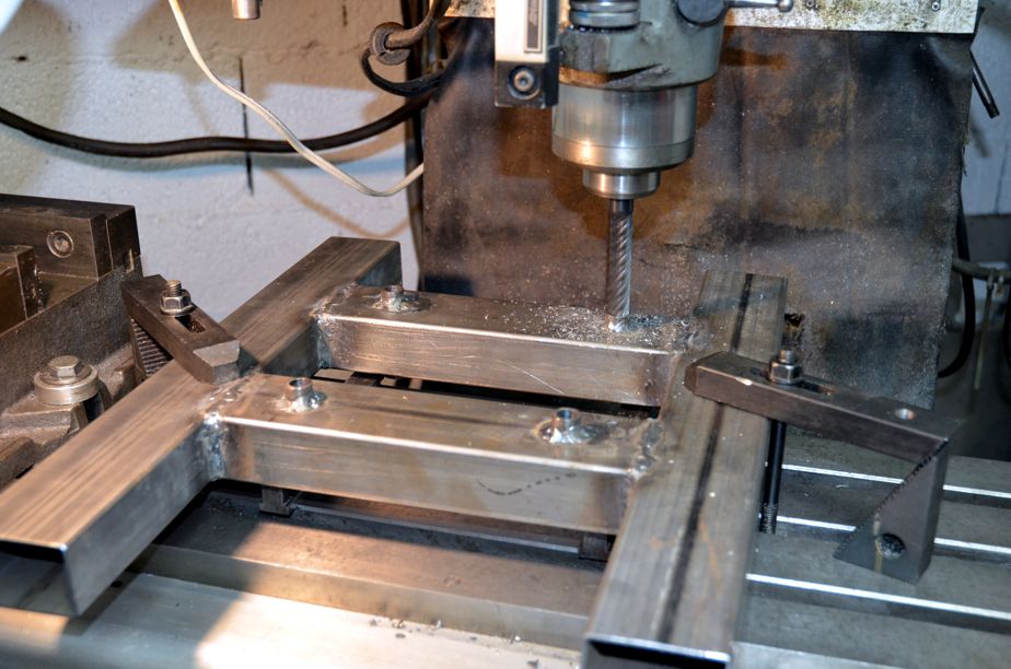
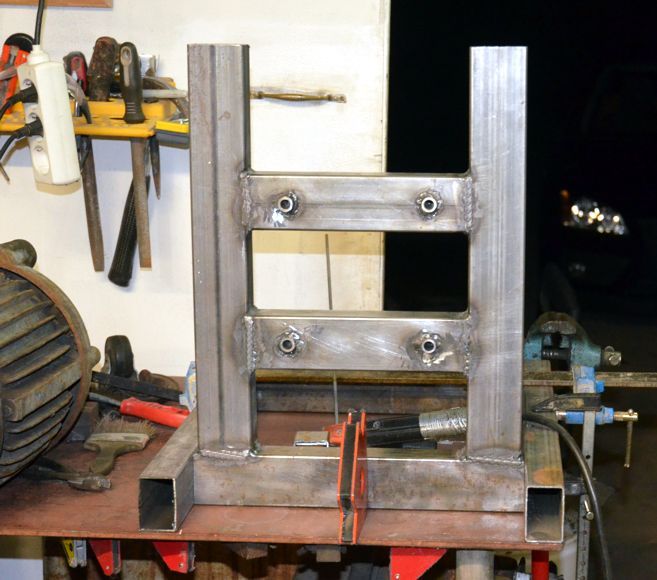
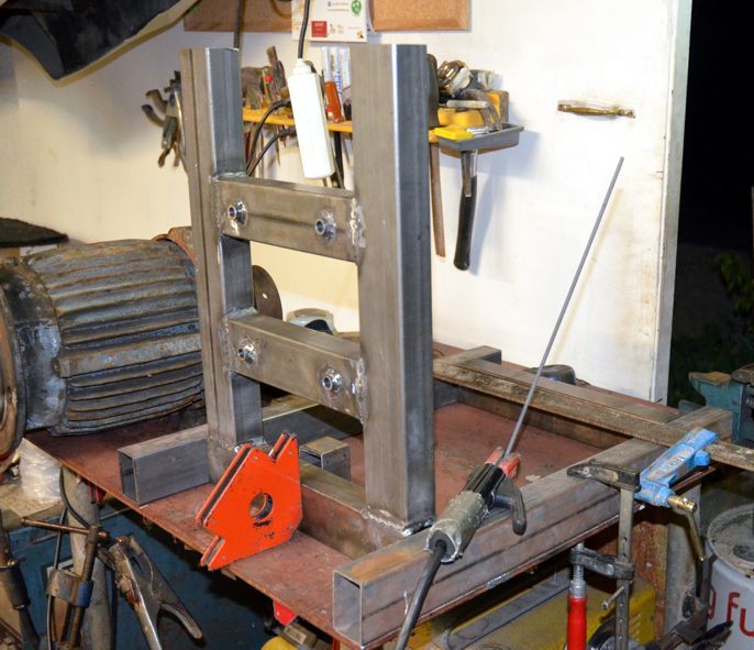
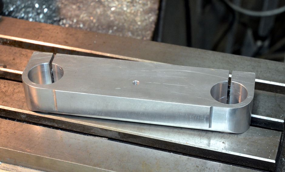
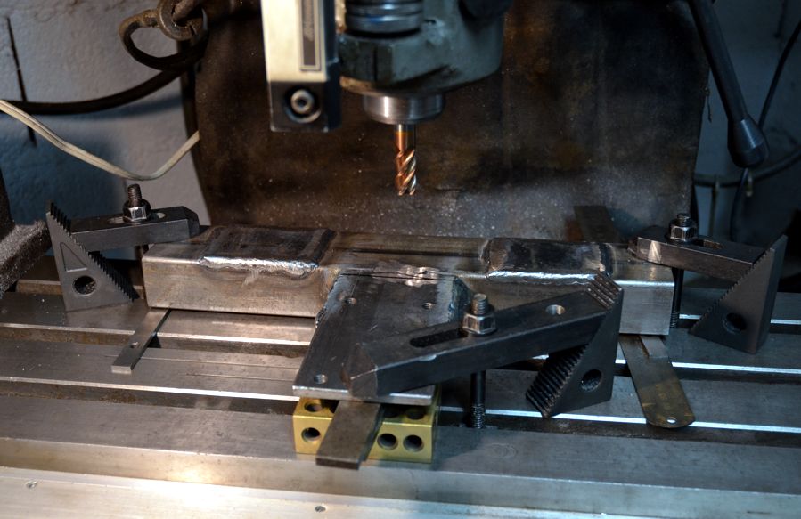
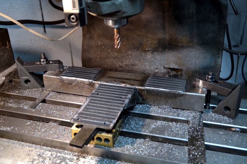
Making the top support bracket for the two uprights. Below are the two fixed lower mountings.
The sub assembly for mounting the bearing block and mountings for the uprights.
**** Photo limit reached. To be continued.


 Reply With Quote

Bookmarks