
 LinkBack URL
 About LinkBacks


Alan,Originally Posted by olderdan

I knew this would capture your attention. Grinding with a motorcycle content, how could it not?
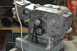
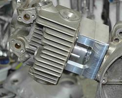
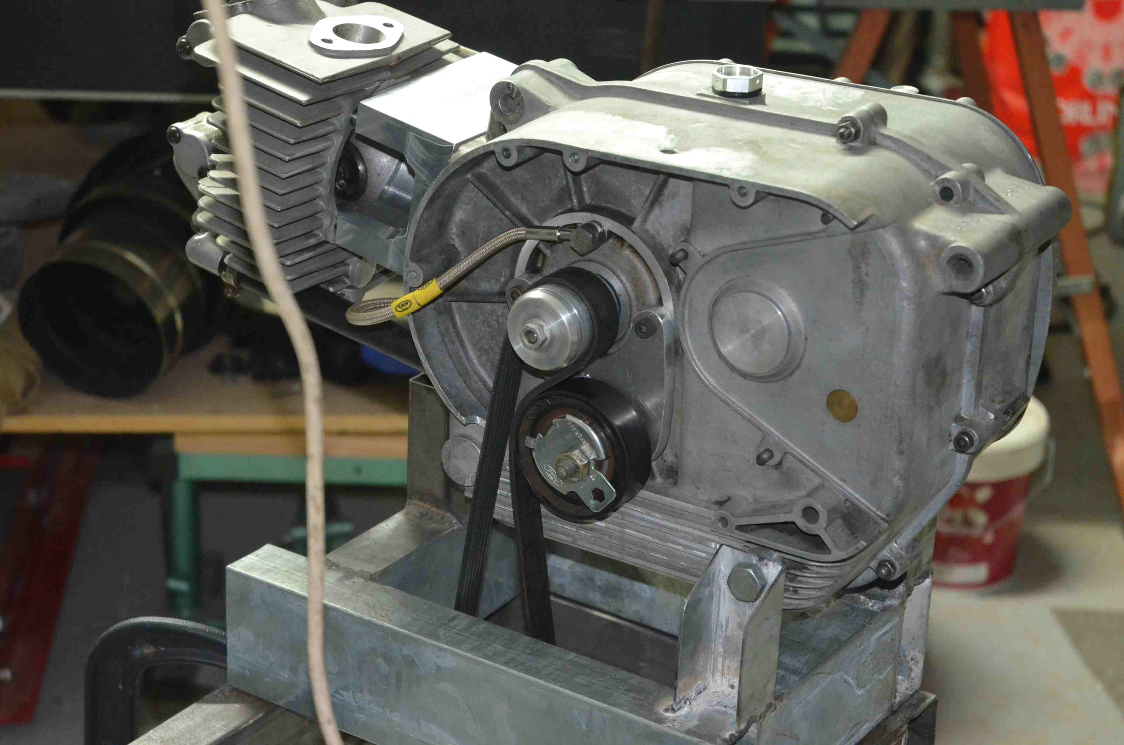
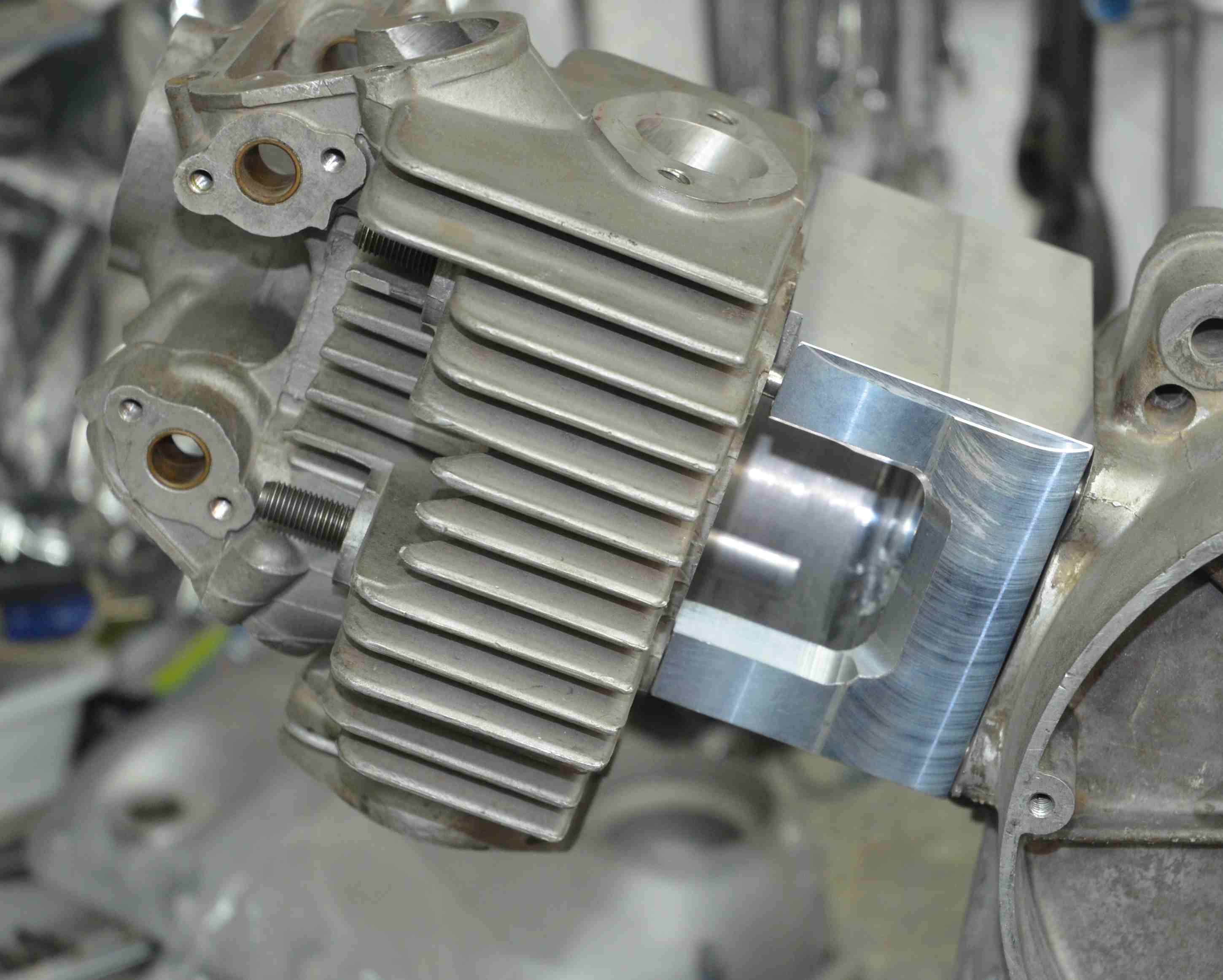
I have written some software to synthesise cam profiles given certain inputs and limits. I have also built a setup for testing cams and viewing in slow motion with a triggered strobe light. This is basically an engine shell with a stripped and balanced crank to drive a cam under test. This is belt driven by a 6 hp motor. I have a dummy cylinder with viewing ports etc. Anyway, I want to made cams to the profile calculated by my synthesis software in order to validate (or not) the software. Well the software is only the messenger, the real test is whether I know what I am doing. This may be of interest https://www.youtube.com/playlist?lis...SvlfD6C_oAHYK3
That is reason no.1 for making the cam grinder, no.2 is as you surmise for my own race bikes. There is a no.3 reason. I have a mate down under who wants to make cams for ancient JAPs, these are not available in the average hardware shop. He has a cylindrical grinder that he wants convert along the lines that I plan with my lathe.
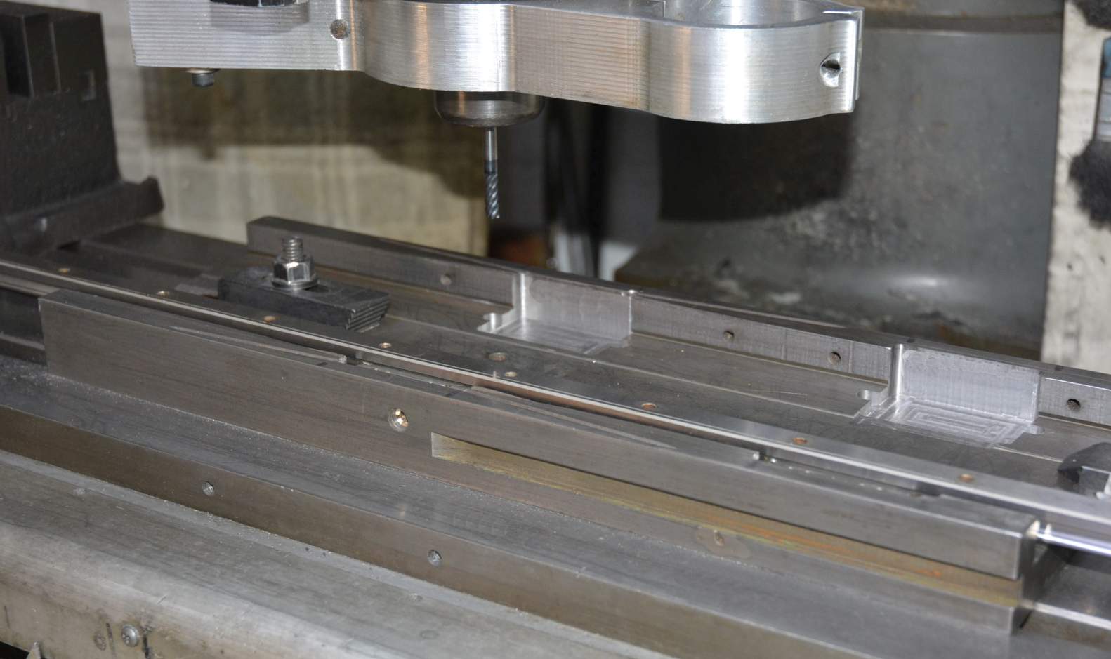
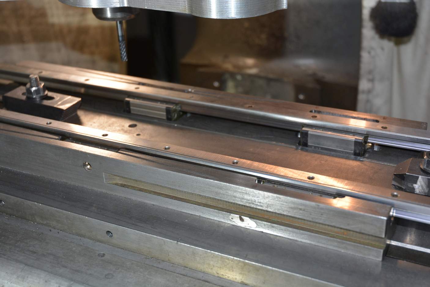
For some time I have been thinking about converting my lathe to linear rails on the X axis but it always seemed like too much work until a couple of nights ago when I saw that it could be done very easily as described in the video. I have the slides on order but they are not due until between 27/12 and 19/01. Impatience got the better of me this morning and I did the modifications to the cross slide from the old larger lathe to take the slides. I was able to test fitting and function because I have the same type of slides, only longer, for another project. There is not much more that I can do now until the new slides arrive. There is some work to do on the saddle of the lathe but that would put the lathe out of action, so that also has to wait for the slides. Here are some pix of this morning's work.
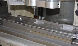
Click for full size.
and some of the cam test device

 Reply With Quote

Bookmarks