Free 186 More Best Homemade Tools eBook:  
New: 300+ fresh build posts/day from 275 forums → BuildThreads.com

User Tag List

Results 1 to 1 of 1

Thread: Trailer Wheel Hub Repair

Threaded View

  1. #1
    Supporting Member hemmjo's Avatar
    Join Date
    Feb 2017
    Posts
    3,301
    Thanks
    410
    Thanked 2,131 Times in 1,230 Posts

    hemmjo's Tools

    Trailer Wheel Hub Repair

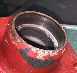
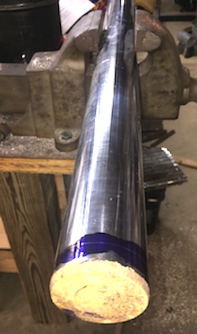
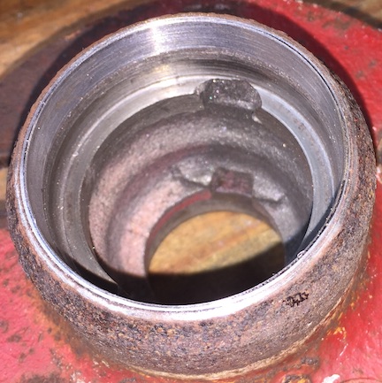
    I have a small home made utility trailer with a damaged wheel hub.
    Link Question on Wheel Hub Repair

    A bearing went bad and damaged one of the hubs. (My fault, lack of maintenance)
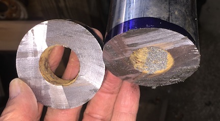
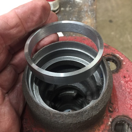
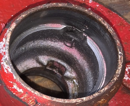
    Good hub with the bad one. The lack of paint and amount of rust tell me this has been
    failing for quite a while

    Click image for larger version. 

Name:	01 Good Hub.jpg 
Views:	43 
Size:	30.5 KB 
ID:	49997 Click image for larger version. 

Name:	02 worn.jpg 
Views:	36 
Size:	32.1 KB 
ID:	49998

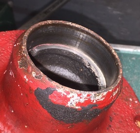
    To begin the repair it I bored the damaged area, where the seal fits.

    Click image for larger version. 

Name:	03 bored.jpg 
Views:	42 
Size:	67.4 KB 
ID:	49999

    Then needed to made a bushing to fit into the new bore.
    I have had a broken rod from a hydraulic cylinder around the
    shop for over 40 years. Too nice a piece of steel to sell for scrap.

    Click image for larger version. 

Name:	04 broken hydraulic rod.jpg 
Views:	41 
Size:	41.9 KB 
ID:	50000

    The seal end already had a hole so I took a slice off that end.

    Click image for larger version. 

Name:	05 donut cut.jpg 
Views:	39 
Size:	34.3 KB 
ID:	50001

    Face first side

    Click image for larger version. 

Name:	06 bushing face.jpg 
Views:	42 
Size:	62.0 KB 
ID:	50002

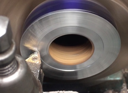
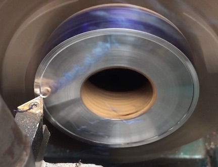
    I have recently begun using carbide more often. It was a necessity for this steel.
    When facing, the relation of cutting speed to surface finish became very evident.

    Notice the matte finish and the cool chip in this frame from a video

    Click image for larger version. 

Name:	07 cool chips.jpg 
Views:	43 
Size:	36.3 KB 
ID:	50003

    As surface speed increased as diameter increased,
    the chips turned blue and surface finish like a mirror.

    Click image for larger version. 

Name:	08 hot chips.jpg 
Views:	38 
Size:	39.4 KB 
ID:	50004

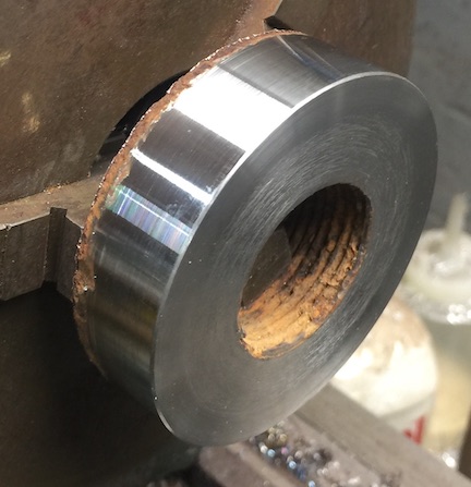
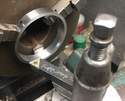
    Holding the part inside the bore to turn the OD to 0.004 under the
    hub bore and and begin to cut the thickness.

    Click image for larger version. 

Name:	09 turn OD.jpg 
Views:	44 
Size:	49.2 KB 
ID:	50005

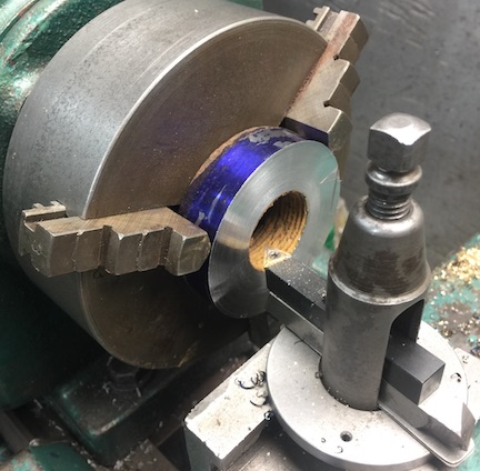
    Then holding on the OD, began boring the ID.

    Click image for larger version. 

Name:	10 set for boring.jpg 
Views:	40 
Size:	55.7 KB 
ID:	50006

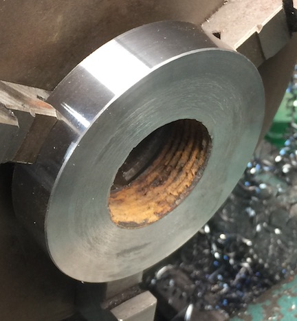
    As boring progressed I realized that jaw pressure might
    distort the bushing.

    Click image for larger version. 

Name:	11 bore progress.jpg 
Views:	38 
Size:	48.5 KB 
ID:	50007

    The finished wall thickness will only be about 0.050”.
    Each cut made me more concerned about distortion. I stopped
    when the wall thickness got close to 0.150”

    Click image for larger version. 

Name:	12 bushing bored.jpg 
Views:	47 
Size:	44.4 KB 
ID:	50008

    Ready to install

    Click image for larger version. 

Name:	13 bush and hub.jpg 
Views:	36 
Size:	55.0 KB 
ID:	50009

    Test Fit

    Click image for larger version. 

Name:	14 bush test fit.jpg 
Views:	41 
Size:	61.2 KB 
ID:	50010

    I had a couple of initial ideas for installing the bushing.
    After considering a press fit, I decided to use adhesive.
    JB weld and Red Loctite came to mind. When looking for
    the Red LocTite, I found a bottle of LocTite 680 Bearing
    Retainer in my tool box. The bottle was dated 2019, shelf-life
    Is supposed to be 2 years. I needed to know it is was still good.

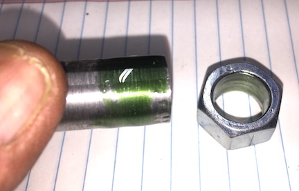
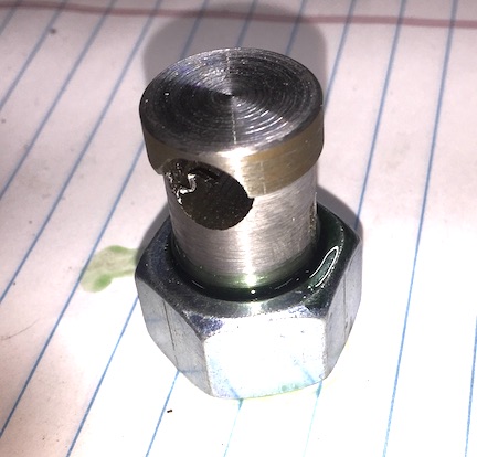
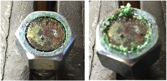
    I made a test by drilling the threads out of a nut and using the
    680 to “glue” it to a smooth piece of steel.

    Click image for larger version. 

Name:	15 LocTite 680 Test.jpg 
Views:	41 
Size:	31.2 KB 
ID:	50011

    Click image for larger version. 

Name:	16 LocTite 680 Test.jpg 
Views:	41 
Size:	47.2 KB 
ID:	50012

    After curing a couple of days I broke them apart, holding the shaft in the
    Vise and using a toque wrench. Beginning at 25 pound-foot, increasing
    by 5 pounds until it failed. It held100 pound foot. 105 pound foot broke the bond.

    Click image for larger version. 

Name:	17 test.jpg 
Views:	48 
Size:	200.9 KB 
ID:	50013

    I have no data, but that seems like a good enough bond to hold the bushing.
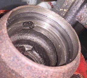
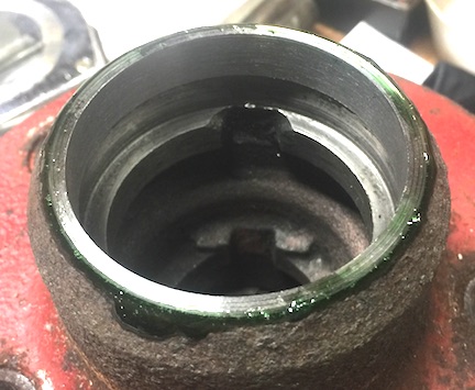
    I used LocTite 680 bearing retainer to install the bushing in the hub.
    Then let it cure for a couple of days.

    Click image for larger version. 

Name:	18 bush installed.jpg 
Views:	40 
Size:	54.7 KB 
ID:	50014

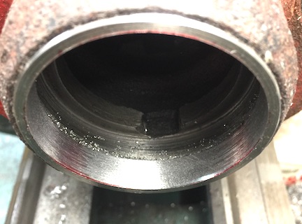
    I took light boring cuts of 0.005 (.0025 DOC) to avoid
    heating the LocTite too much. It became apparent during the
    first pass that the chuck had distorted the bushing.
    The skipping cuts could be easily heard, 3 times,
    equally around the bore. Before making the second pass I put
    layout die in the bore which clearly showed the 3 jaw locations.

    Click image for larger version. 

Name:	19 distorted ID.jpg 
Views:	36 
Size:	45.2 KB 
ID:	50015

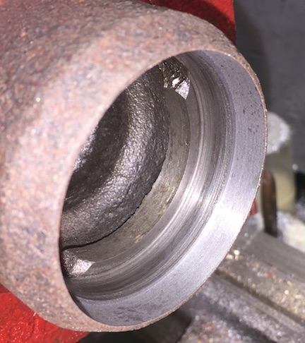
    The 3rd pass almost eliminated the distortion.

    Click image for larger version. 

Name:	20 distorted ID 2.jpg 
Views:	41 
Size:	41.0 KB 
ID:	50016

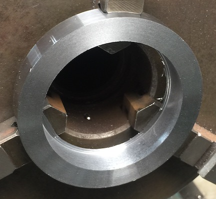
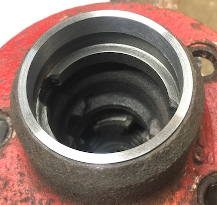
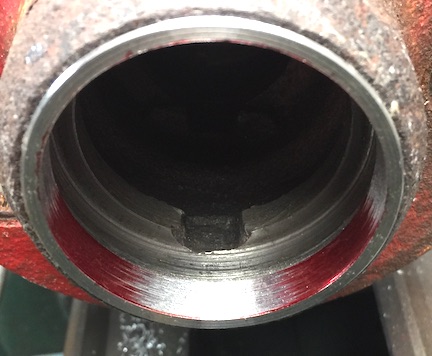
    The bushed hub with its un-damaged brother. You can see,
    the transition between new and original but I cannot feel it

    Click image for larger version. 

Name:	21 finished repair.jpg 
Views:	40 
Size:	76.3 KB 
ID:	50017

    Click image for larger version. 

Name:	22 undamaged hub.jpg 
Views:	39 
Size:	68.2 KB 
ID:	50018

    Now waiting for Speedi-Sleeves for the spindles

  2. The Following 2 Users Say Thank You to hemmjo For This Useful Post:

    emu roo (Nov 18, 2025), nova_robotics (Nov 18, 2025)

Thread Information

Users Browsing this Thread

There are currently 1 users browsing this thread. (0 members and 1 guests)

Bookmarks

Posting Permissions

  • You may not post new threads
  • You may not post replies
  • You may not post attachments
  • You may not edit your posts
  •