Free 186 More Best Homemade Tools eBook:  
New: 300+ fresh build posts/day from 275 forums → BuildThreads.com

User Tag List

Results 1 to 10 of 13

Thread: Turning Matching External/Internal Tapers

Hybrid View

  1. #1
    Supporting Member rgsparber's Avatar
    Join Date
    Nov 2012
    Location
    Phoenix, AZ
    Posts
    1,392
    Thanks
    802
    Thanked 3,091 Times in 741 Posts

    rgsparber's Tools

    Turning Matching External/Internal Tapers

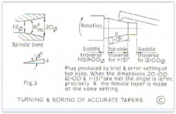
    One of the many useful operations possible with a lathe is to cut tapers. These can be external or internal. Sometimes an external taper is cut and I want a matching internal taper. This article presents a procedure that requires no math or measuring to set up to cut the internal taper.

    If you are interested, please see

    https://rick.sparber.org/MatchingTapers.pdf

    Your comments are welcome. All of us are smarter than any one of us.


    Thanks,

    Rick
    Rick

  2. The Following 12 Users Say Thank You to rgsparber For This Useful Post:

    57_210 (Dec 31, 2022), bigtrev8xl (Nov 29, 2019), Carnel (Nov 29, 2019), davesrepair (Aug 14, 2024), emu roo (Aug 13, 2024), FEM2008 (Nov 28, 2019), Jon (Nov 28, 2019), mklotz (Nov 28, 2019), NortonDommi (Dec 9, 2019), olderdan (Nov 28, 2019), Philip Davies (Aug 14, 2024), Seedtick (Nov 28, 2019)

  3. #2
    Supporting Member mklotz's Avatar
    Join Date
    Aug 2015
    Location
    LA, CA, USA
    Posts
    3,720
    Thanks
    376
    Thanked 7,190 Times in 2,348 Posts

    mklotz's Tools
    Very clever, Rick. Thanks.

    Just to add to this discussion, not meant as a criticism of your method, here's how I've done it before.

    Set the compound to track the angle of the rear side of the male taper.

    Now mount a boring bar and, lathe running in reverse, cut the (male) taper on the back side of the workpiece.

    The lathe is already configured to cut the female taper conventionally.

    If your lathe has a chuck that threads onto the spindle, you need to be careful making the male cut. Too deep a cut and the chuck can unscrew. I've machined tapers this way but kept the cut to only a few thousandths per pass.
    ---
    Regards, Marv

    Smart phones are to people what laser pointers are to cats
    Homo sapiens is a goal, not a definition

  4. The Following 3 Users Say Thank You to mklotz For This Useful Post:

    Christophe Mineau (Nov 28, 2019), emu roo (Jun 30, 2025), FEM2008 (Nov 28, 2019)

  5. #3
    Supporting Member rgsparber's Avatar
    Join Date
    Nov 2012
    Location
    Phoenix, AZ
    Posts
    1,392
    Thanks
    802
    Thanked 3,091 Times in 741 Posts

    rgsparber's Tools
    Quote Originally Posted by mklotz View Post
    Very clever, Rick. Thanks.

    Just to add to this discussion, not meant as a criticism of your method, here's how I've done it before.

    Set the compound to track the angle of the rear side of the male taper.

    Now mount a boring bar and, lathe running in reverse, cut the (male) taper on the back side of the workpiece.

    The lathe is already configured to cut the female taper conventionally.

    If your lathe has a chuck that threads onto the spindle, you need to be careful making the male cut. Too deep a cut and the chuck can unscrew. I've machined tapers this way but kept the cut to only a few thousandths per pass.
    Marv,

    I really like your approach! By not disturbing the compound, you get exactly the same taper for external and internal. Glad you warned about running in reverse with a screw-on chuck.

    Thanks!

    Rick
    Rick

  6. The Following User Says Thank You to rgsparber For This Useful Post:

    emu roo (Jun 30, 2025)

  7. #4
    Supporting Member olderdan's Avatar
    Join Date
    Jun 2016
    Posts
    811
    Thanks
    1,479
    Thanked 1,785 Times in 520 Posts

    olderdan's Tools
    Adding further to the taper turning subject, Joe Peiczynski has an excellent video on his channel here.
    for setting the compound slide spot on first time for known tapers without a master.

  8. The Following 4 Users Say Thank You to olderdan For This Useful Post:

    albertq (Aug 13, 2024), bigtrev8xl (Nov 29, 2019), emu roo (Jun 30, 2025), rgsparber (Nov 28, 2019)

  9. #5
    Supporting Member rgsparber's Avatar
    Join Date
    Nov 2012
    Location
    Phoenix, AZ
    Posts
    1,392
    Thanks
    802
    Thanked 3,091 Times in 741 Posts

    rgsparber's Tools
    Quote Originally Posted by olderdan View Post
    Adding further to the taper turning subject, Joe Peiczynski has an excellent video on his channel here.
    for setting the compound slide spot on first time for known tapers without a master.
    Olderdan,

    Joe Pie is one of the all-time master teachers. I love his use of applied mathematics in the shop. Very powerful.

    I understand his angle setting method but I didn't catch how he sets the starting diameter.

    Rick
    Rick

  10. The Following 2 Users Say Thank You to rgsparber For This Useful Post:

    Christophe Mineau (Nov 28, 2019), emu roo (Jun 30, 2025)

  11. #6
    Supporting Member olderdan's Avatar
    Join Date
    Jun 2016
    Posts
    811
    Thanks
    1,479
    Thanked 1,785 Times in 520 Posts

    olderdan's Tools
    Quote Originally Posted by rgsparber View Post
    Olderdan,

    Joe Pie is one of the all-time master teachers. I love his use of applied mathematics in the shop. Very powerful.

    I understand his angle setting method but I didn't catch how he sets the starting diameter.

    Rick
    Hi Rick, not sure what you mean by a start dia, all Joe Pie is doing is measuring three sides of a triangle so angle must be correct. I know you get that. A start dia on the work can then be anything you want. If it has to be a size I usually turn a short parallel reference dia and run up the taper from there.

  12. The Following User Says Thank You to olderdan For This Useful Post:

    emu roo (Jun 30, 2025)

  13. #7
    Supporting Member rgsparber's Avatar
    Join Date
    Nov 2012
    Location
    Phoenix, AZ
    Posts
    1,392
    Thanks
    802
    Thanked 3,091 Times in 741 Posts

    rgsparber's Tools
    Joe Pie mentioned in passing that he was going to explain how to set the diameter at the entrance to the cone. Either it was super quick or he never explained it.

    Rick
    Rick

  14. The Following User Says Thank You to rgsparber For This Useful Post:

    emu roo (Jun 30, 2025)

  15. #8

    Join Date
    Dec 2016
    Posts
    9
    Thanks
    1
    Thanked 18 Times in 2 Posts

    mrehmus2's Tools
    The only caveat I see with this approach is that unless the cutting tool is on the axial center-line of the spindle, the taper cut will have a concave or convex bow in it. Or so I am told by one master machinist I know.
    Also, you can use a line of chalk on the male taper to check the fit in the female taper. It should be smoothly wiped if the fit is good.

  16. #9
    Supporting Member olderdan's Avatar
    Join Date
    Jun 2016
    Posts
    811
    Thanks
    1,479
    Thanked 1,785 Times in 520 Posts

    olderdan's Tools
    Quote Originally Posted by rgsparber View Post
    Joe Pie mentioned in passing that he was going to explain how to set the diameter at the entrance to the cone. Either it was super quick or he never explained it.

    Rick
    Hi Rick, now I know what you are aiming for I only know two ways of doing that, One of the most difficult things to measure is the large end of an internal taper. I either make a gauge like this.
    Turning Matching External/Internal Tapers-tapers.jpg

    Or turn a short register on the front of the bore which can then be removed. I would be interested in an updated method from Joe Pie, maybe he would respond to a request.
    Regards.

  17. The Following User Says Thank You to olderdan For This Useful Post:

    emu roo (Jun 30, 2025)

  18. #10
    Supporting Member mklotz's Avatar
    Join Date
    Aug 2015
    Location
    LA, CA, USA
    Posts
    3,720
    Thanks
    376
    Thanked 7,190 Times in 2,348 Posts

    mklotz's Tools
    Another way to measure a hole like the exit of an internal taper is to measure how far a precision tooling ball seats into the hole, then do a bit of mathematics to obtain the diameter of the hole.

    The accuracy of this method depends heavily on the condition of the hole edge. There can be no chamfer or burs and the ball can not be pressed into the hole.

    The associated math looks like this...

    Let:

    R = radius of tooling ball
    H = distance ball descends into hole
    D = diameter of hole

    Then:

    Z = R - H
    A = 2 * ACS (Z/ R)
    D = 2 * R * SIN (0.5*A)
    ---
    Regards, Marv

    Smart phones are to people what laser pointers are to cats
    Homo sapiens is a goal, not a definition

Thread Information

Users Browsing this Thread

There are currently 1 users browsing this thread. (0 members and 1 guests)

Tags for this Thread

Bookmarks

Posting Permissions

  • You may not post new threads
  • You may not post replies
  • You may not post attachments
  • You may not edit your posts
  •