Free 186 More Best Homemade Tools eBook:  
New: 300+ fresh build posts/day from 275 forums → BuildThreads.com

User Tag List

Results 1 to 10 of 15

Thread: Ball joint removal and install tool for GM vehicles

Threaded View

  1. #1
    Supporting Member Frank S's Avatar
    Join Date
    Aug 2015
    Location
    Peacock TX
    Posts
    12,611
    Thanks
    2,677
    Thanked 11,100 Times in 5,384 Posts

    Frank S's Tools

    Ball joint removal and install tool for GM vehicles

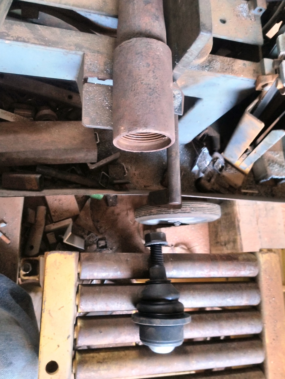
    I am rebuilding the entire front end of a GMC 2500 HD 4x4
    To replace the lower ball joints I needed some special tools and had to make a unique set up to press them out
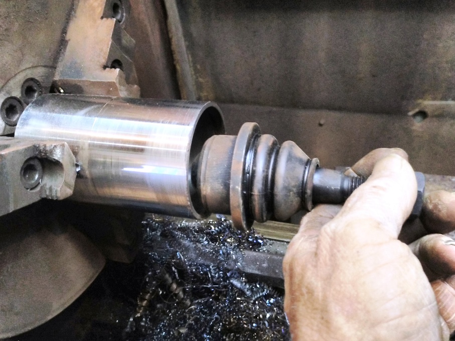
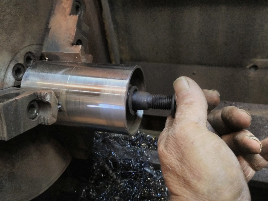
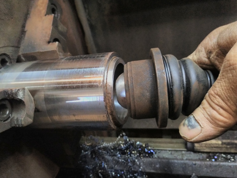
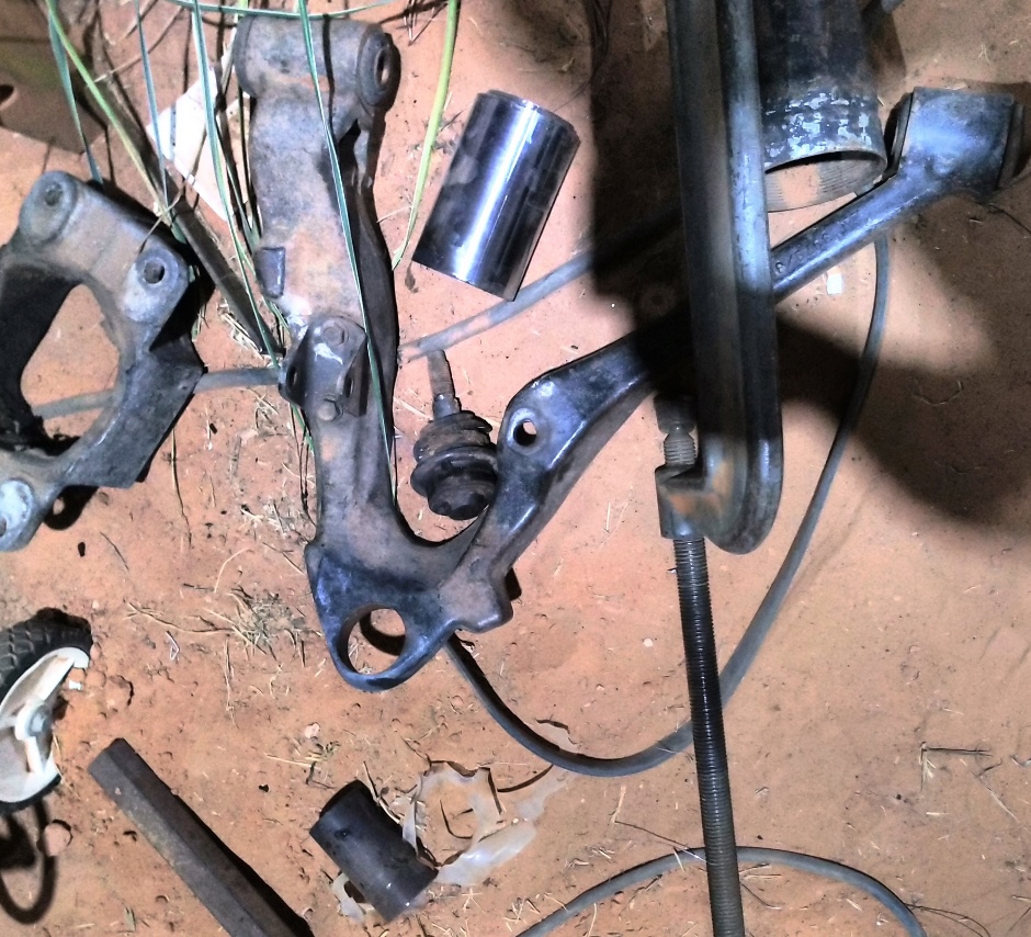
    I started out by cutting the coupling from a piece of 2 3/8" oil field tubing
    Click image for larger version. 

Name:	IMG_20230501_155116bjt.jpg 
Views:	289 
Size:	428.0 KB 
ID:	45362
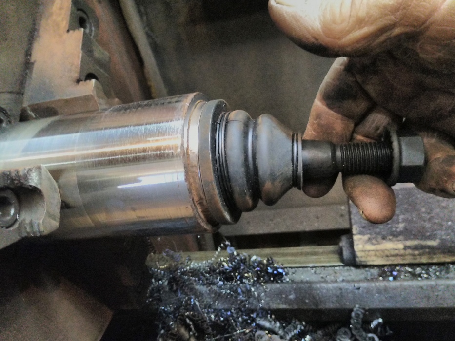
    Then machined the threads out of 1 end to fit over the flange of the ball joint.
    Click image for larger version. 

Name:	IMG_20230501_162444bjt.jpg 
Views:	284 
Size:	267.5 KB 
ID:	45363
    Click image for larger version. 

Name:	IMG_20230501_162450bjt.jpg 
Views:	263 
Size:	250.0 KB 
ID:	45364
    Then machined the Id of the tubing stub to fit over the od rubber boot this is also the same diameter as the boss that presses into the control arm
    Click image for larger version. 

Name:	IMG_20230501_162540bjt.jpg 
Views:	273 
Size:	277.7 KB 
ID:	45365
    Click image for larger version. 

Name:	IMG_20230501_162555bjt.jpg 
Views:	270 
Size:	304.7 KB 
ID:	45366
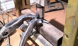
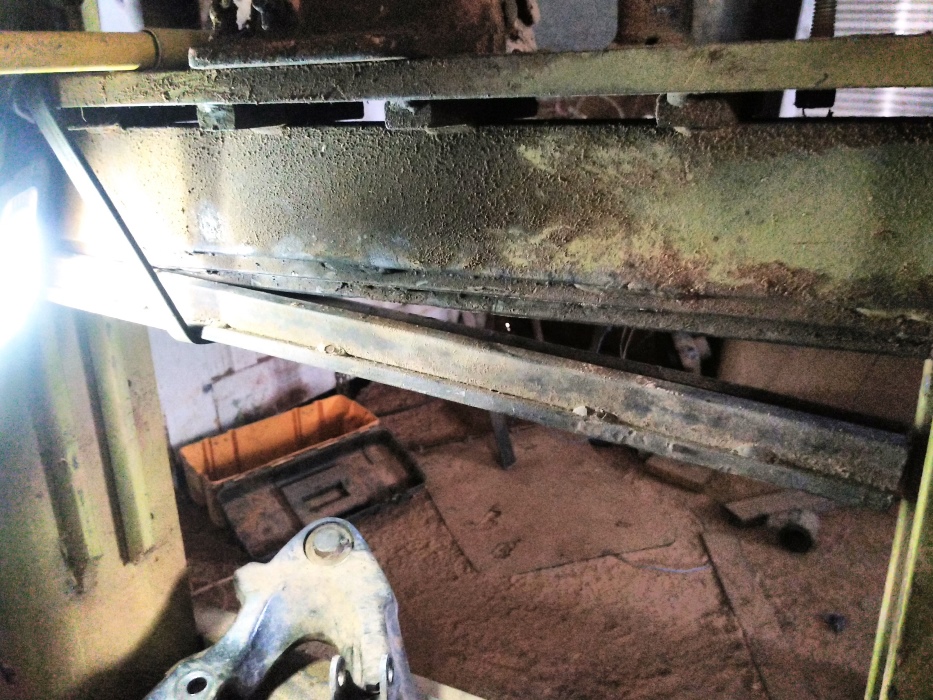
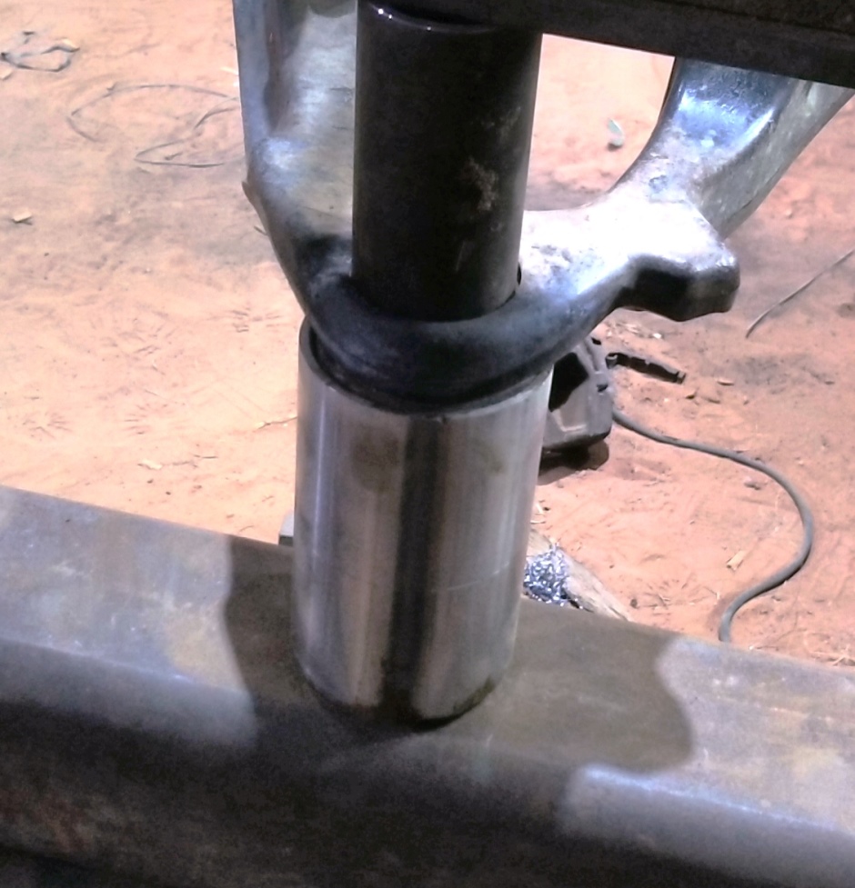
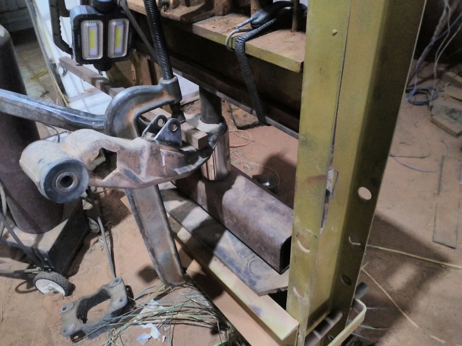
    Next comes the set up. since I have a metal break punch permanently mounted to my shop press I suspended the bottom die under the punch with rubber tarp straps so I would have a flat pressing surface
    Click image for larger version. 

Name:	IMG_20230501_180204bjt.jpg 
Views:	242 
Size:	347.5 KB 
ID:	45367
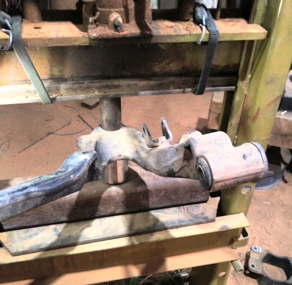
    After getting everything aligned up and ready to press the ball joint out
    Click image for larger version. 

Name:	IMG_20230501_180451bjt.jpg 
Views:	285 
Size:	321.0 KB 
ID:	45368
    I noticed that the arm did not have a flat surface around half of the ball joint flange
    Click image for larger version. 

Name:	IMG_20230501_180502bjt.jpg 
Views:	258 
Size:	250.0 KB 
ID:	45369
    I needed a way to keep the arm from cocking up on one side to do this I used my 16" heavy duty C clamp to hold it down
    Click image for larger version. 

Name:	IMG_20230501_181435njts.jpg 
Views:	274 
Size:	301.6 KB 
ID:	45370
    Maxed out the 8 ton hydraulic jack added just a little heat and this is the position everything wound up when the ball joint slipped out of the control arm
    Click image for larger version. 

Name:	IMG_20230501_181931bjts.jpg 
Views:	260 
Size:	392.0 KB 
ID:	45371
    pressing the new joint in place only required the tool and a simple 1/2" cylindrical spacer under the arm
    Click image for larger version. 

Name:	IMG_20230501_182711bji.jpg 
Views:	228 
Size:	217.1 KB 
ID:	45372
    Never try to tell me it can't be done
    When I have to paint I use KBS products

  2. The Following 7 Users Say Thank You to Frank S For This Useful Post:

    baja (May 5, 2023), emu roo (Mar 16, 2026), Jon (May 1, 2023), metric_taper (May 2, 2023), mr mikey (May 3, 2023), Scotty1 (May 2, 2023), sossol (May 2, 2023)

Thread Information

Users Browsing this Thread

There are currently 1 users browsing this thread. (0 members and 1 guests)

Bookmarks

Posting Permissions

  • You may not post new threads
  • You may not post replies
  • You may not post attachments
  • You may not edit your posts
  •