I think it is a "rapid traverse" screw.
I think it is a "rapid traverse" screw.
yup,I agree.or making soft serve icecream nozzels
Boring mill at the McKees Rocks Machine and Erecting Shop. Pennsylvania, 1904.
Fullsize image: https://diqn32j8nouaz.cloudfront.net...l_fullsize.jpg
https://diqn32j8nouaz.cloudfront.net...oring_mill.jpg
This ~60 incher somewhat like my Kansas job; besides straight rams, it was turret and full 6'. Like driving a really big tractor or something!
A lot of feature overlap in verticals, blurring distinct models. IMNSHO due to the space needed, not only machine, loading parts always need consideration. Anyway, logic tells me overlap is a sales pitch. Verticals aren't so rare, but a shop using them often have more than one, ranging in size. Part size (RPM/ FPM ranges) not so broad compared to engine lathes.
General Iron Works in Englewood, Colorado had a vertical boring mill that "swung" 46 feet in diameter. They turned some kind of reactor weldments. They're gone, I don't know where it went after they closed. They also had a "pit lathe" - a horizontal lathe with a large T shaped pit. It would swing 27 feet in diameter at the face plate. Only ran it for a few shifts back in the early 70's, I don't know who made it, might have been "shop built".
That's not boring at all! Give yourself some credit. That machine looks incredibly exciting!
(Just in case the irony doesn't come across in print, I know what a boring mill is. It's just a Dad joke.)
It's so "Boring"........yup, Class A Dad joke. Horizontals aren't so exiting, but verticals are; something about mass of chuck and part turning demands a bit extra attention. I like good sized machinery, they'll be biggest I'll ever get to run, so thrill factor always there.
But my favorite Dad joke is this one; by of course MY Dad.....
Brought him in one day for a tour, walked the place; spun up spindles, cycled punch-presses, demonstrated variety of grinders, you know the drill [that one counts too!]. Asked lots of questions, especially Inspection area, surface plates, manual coordinate machines, instruments. They had a big J&L comparator, 30", he wanted to know "why do they have a voting booth?".
the voting booth is to decide on weather somebody want that part or not...
Im reel good at serfacing plates, I just finished dinner and the plate is swarf free.....ok not a dad joke..sorry. my wife did tell my 86 year old mom a joke tonight at dinner.... little johnny was in school when the teacher was going over the male and female body posters she had put up...she then asked for questions after telling the class all men look like this and all females look like this....thats when little johnny took over and tole her she was rong....no johnny this is correct. He then informed her that his daddy had 2 of those!!! she replied thats impossible. he said no my daddy has one he pees through and one that mamma uses to brush her teeth with........ I thought my mom was going to keel over.
I like your Dad.
[QUOTE=marksbug;180367]... my wife did tell my 86 year old mom a joke tonight at dinner.... /QUOTE]
I like your wife!!
Attachment 39415
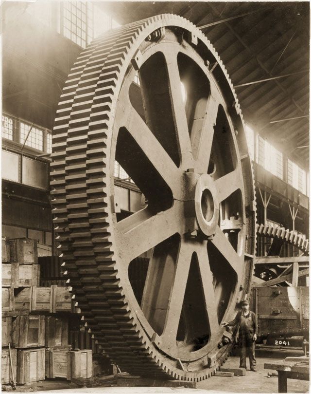
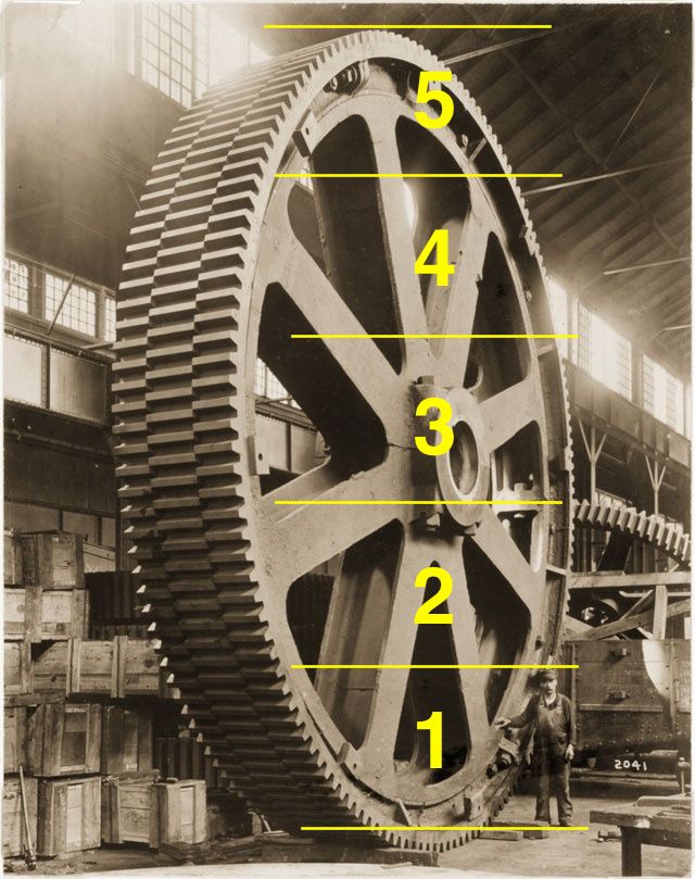
There is something so satisfying about huge cogs
"There is something so satisfying about huge cogs"
Especially when they mesh...
Guessing that is about 5m (men) tall.
Attachment 39418
Thresher Varnish Company. Dayton, Ohio, 1937.
Fullsize image: https://diqn32j8nouaz.cloudfront.net...e_fullsize.jpg
https://diqn32j8nouaz.cloudfront.net...ny_machine.jpg
414
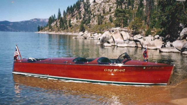
When I see the word varnish I always think of the brightwork on my sailboats.
Sadly the word polyurethane does not have the same effect.
sail boat?? really???? I cant do sail boats, just too slow for me,Ive been on a few kinds fast ones( well the owners said they were fast) I know some people that race them, my crazy sister set a world reckord back in the 90's ,I think it was la to Australia or something like that. she was supposed to do another on the same boat a few years lator, a week before she was to set sail it went up in flames. I used to machine&build engines and maintain lots of ***** boats.I ran a 40' douglass skater,lake X record holder one time just over 150 mph in the bay (blow ninnercooled big block chevy powered x2),I just re worked the top end and it needed test drive...I miss doing that stuff.) I would of pegged you for a motor boat...speed boat guy. but yes I understand the poluyrathane.... VS real bright work.
I only use Epifanes...
Attachment 39447
Unquestionably what the character meant saying "I used to run the Gulf in that speedboat's grand-daddy".Quote:
Originally Posted by IntheGroove
THATS GOOD STUFF, THE WIFE SELLS IT. she says it's the best and possiably the only real clear quality varnish left.
Aluminum press. Aluminum Company of America. 1950.
Fullsize image: https://diqn32j8nouaz.cloudfront.net...s_fullsize.jpg
https://diqn32j8nouaz.cloudfront.net...inum_press.jpg
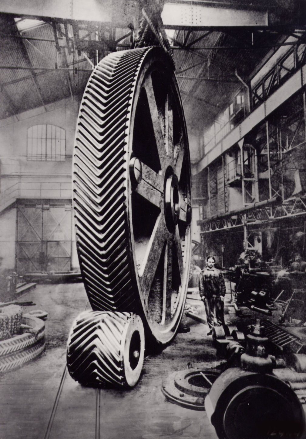
Are those big gears machined with the chevron shaped teeth? or is that two big gears put together to make one. Very impressive either way, I just have trouble imaging how they would machine the chevron.
Machined as one gear...
Attachment 39564
Ah, I see they are created in several different ways.... as explained on https://en.wikipedia.org/wiki/Herringbone_gear
"A disadvantage of the herringbone gear is that it cannot be cut by simple gear hobbing machines, as the cutter would run into the other half of the gear. Solutions to this have included assembling small gears by stacking two helical gears together, cutting the gears with a central groove to provide clearance, and (particularly in the early days) by casting the gears to an accurate pattern and without further machining. With the older method of fabrication, herringbone gears had a central channel separating the two oppositely-angled courses of teeth. This was necessary to permit the shaving tool to run out of the groove. The development of the Sykes gear shaper made it possible to have continuous teeth with no central gap. Sunderland, also in England, also produced a herringbone cutting machine. The Sykes uses cylindrical guides and round cutters; the Sunderland uses straight guides and rack-type cutters. The W. E. Sykes Co. dissolved in 1983–1984. Since then it has been common practice to obtain an older machine and rebuild it if necessary to create this unique type of gear. Recently, the Bourn and Koch company has developed a CNC-controlled derivation of the W. E. Sykes design called the HDS1600-300. This machine, like the Sykes gear shaper, has the ability to generate a true apex without the need for a clearance groove cut around the gear. This allows the gears to be used in positive displacement pumping applications, as well as power transmission. Helical gears with low weight, accuracy and strength may be 3D printed."
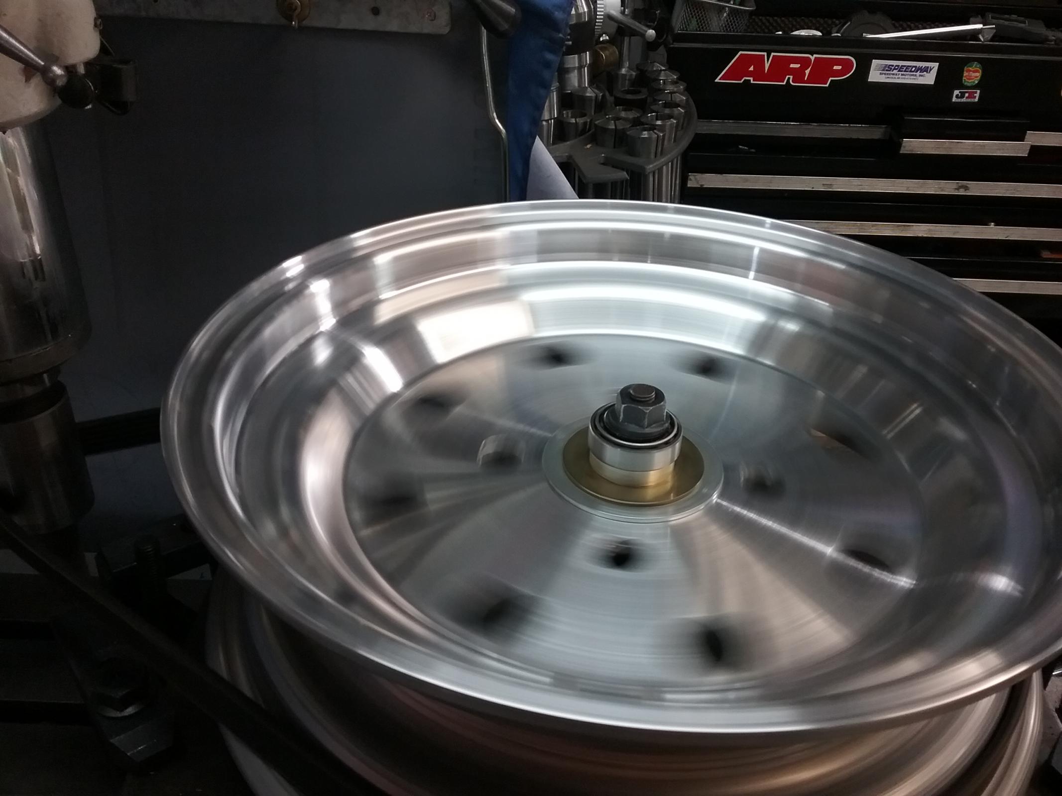
looks like there making the wheels for my racecar!!!! well...I had some that were forged and some that were spun. and some that were ****....I had some CMS wheels on the front of one of my cars...I thought that stood for China Made ****...I was informed those were made in cali.....fornia. I bought them new as I have all my wheels, they were the worst **** Ive ever seen, wobbly as hell, like 2-3mm run out side to side and the bolt pattern wasent even in the center that was off around 2 mm...how the **** can you make **** like that and charge for it???? I put them on my mill squared them up, straightened,recentered the bolt pattern, and added some lightening holes.Attachment 39565. they were oh so much better when I finished.
Double helical cut tooth mill pinions. Mesta Machine Company.
Fullsize image: https://diqn32j8nouaz.cloudfront.net...s_fullsize.jpg
https://diqn32j8nouaz.cloudfront.net...ll_pinions.jpg
Mesta built huge presses and stuff which would use gears and other parts this large.
I get so many questions when I see this BIG old photos;
Where is the rest of that machine, What did they do with it, How BIG was the machine that cut those gears, There must be some serious structure under that wood floor!! Maybe it is just wood laid over concrete to limit damage if something is dropped. etc
Interesting markings on the various bearing sections. I always mark things in similar fashion just incase it is possible to put them back together incorrectly. Those marks appear to be for some other purpose.
I saw some types of these under the Leonardo D. engerneering(I think, something like that,motion.somethen ) mustseeum in milan years ago,so awesome. great way to control back lash and thrust at the same time and adjustable too. I saw oh somuch in that dirt floor machine shop with 4 story mustseeum built over it. I even learned how DOM is made there....I had no idea, and no idea that stuff was going on centurys ago.I need to go back for another look for a few years.
Herringbone gears,,,i worked in a machine shop in 1998-2002 here in OKC , that had 1934 sydney lathe 20 " swing by 6 ft long bed,all the headstock gears were herringbone,6 speeds, u changed speeds by turning a two handed lever when the spindle was barely rotating,,fastest speed was 300,great lathe that could take a 1/4 inch cut all day ,,till a headstock bearing needed replacing or tightening up, which happened about every 6 months..
Yes Good Question,What were they Used for? Where are the Top Caps? Certainly Don't Put Your Fingers Anywhere Near Those Gears When Turning!
It blows my mind to think of how it must have been machining those gears back then, although I don't really know how old this photo is.
Another thing to consider, between the engineer(s) who designed this monstrosity and the machinists that made it, the design and building process has to be so precise to get the backlash correct on those gears. Not sure how you would even adjust that on this machine.
I wonder what it was used for?
Looks like a gears for some large metal rolling equipment. the journals run on solid bearings and I am guessing those puppies will transmit something like 4-5000 HP.Quote:
Originally Posted by mcthistle007
.......or something very much like rolling equipment. Such operations run best not by spur gearing; hypoids and various helical engagements have what it takes.Quote:
Originally Posted by Howder1951
I'm assuming you're in Oklahoma City. I'm gonna get over there one day to see the Cowboy and Western Heritage Museum.
It's probably just a part of a very large machine that they are supplying. Maybe a propulsion assembly for a ship or unique locomotive vehicle. Who knows?
Driving wheel lathe. Pittsburgh and Lake Erie Railroad Company. July, 1904.
Fullsize image: https://diqn32j8nouaz.cloudfront.net...e_fullsize.jpg
https://diqn32j8nouaz.cloudfront.net...heel_lathe.jpg
436
I like the open air electrical switches.
I thought of two operators but there is only one cross slide handle.
The motor appears to be DC...
I an electrician in the Navy and the ship I was on was 240 volt DC, the main distribution switch board was open knife switches just like what Is on the big lathe. The ship was an old merchant marine converted for amphibious assault transporting marines and their equipment with the boats where the front ramp drops. I hated that ship but gained valuable experience. I cringe when I see old open equipment but it seems people were more careful in their jobs.
1000-ton forging press. Puget Sound Naval Shipyard. Kitsap County, WA.
Fullsize image: https://diqn32j8nouaz.cloudfront.net...s_fullsize.jpg
https://diqn32j8nouaz.cloudfront.net...ging_press.jpg