Why? "The term blacksmith derives from iron, formerly called “black metal,” Blacksmiths existed long before any exports out of Africa.
Why? "The term blacksmith derives from iron, formerly called “black metal,” Blacksmiths existed long before any exports out of Africa.
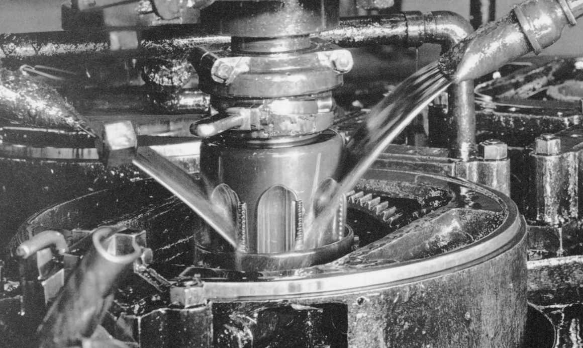
Mesta Machine Company pickling machine.
Fullsize image: https://diqn32j8nouaz.cloudfront.net...2_fullsize.jpg
https://diqn32j8nouaz.cloudfront.net...g_machine2.jpg
Large planer. Pittsburgh and Lake Erie Railroad Company. April, 1904.
Fullsize image: https://diqn32j8nouaz.cloudfront.net...r_fullsize.jpg
https://diqn32j8nouaz.cloudfront.net...rge_planer.jpg
appears to be a machine in use there in the background
And I can hear the operator to left of that "Ok a little bit to starboard, wait , port, now full steam ahead!"...
Roughly size I ran a couple years, 30' and 40'. Any table length requires twice that of bed and ways, but that's why they did such fine work. None of that potential table sag or binding ways of lesser machines, or concentrated wear.
While planers technically operate as 'single point' machines, they have reasonable feed rates, of course lost some time on return stroke. Worked out beneficial on certain kinds of parts, such as weather stripping molds, wing spars, machine skids, and tables of smaller machine tools.
Examine the foot of a large radial drill, I've seen tool marks that indicate planing and scarf milling, both easy work for a planer.
Scarfing of that variety employs a slightly tilted spindle and turning cutter. They step cuts over a bit more than cutter diameter, leaving shallow grooves with narrow lands between, accomplishing part of what scraping does.
Overall, planers did reliable work on parts with very long but small profiled features. Also remains maybe best at undercutting, where an endmill or other rotating cutter just can't enter.
I often wonder how many remain in operation. Extrusion has taken over what long compression molds did, with far more compact machine footprint and tooling.
On the lintel (head) beam it says Plane Field N.J. but there is a shaft blocking my view of the manufacturer's name. Does anybody know who would have built this in Plain Field N.J. more than a century ago?
That would the Pond Machine Tool Company.
I wonder when they went under
The company didn't go under, it was merged with the Niles Tool Works of Hamilton, Oh, and the Bement, Miles Co of Philadelphia, August 15, 1899, to form the Niles, Bement, Pond Co. Pratt & Whitney becoming another division in 1901.
thanks but you tottaly missed...it zinged right over your head... "pond"& "went under" oh well I tried.I better find a day job...
Do ponds go under? Boats, people, ice-skaters, companies go under...
A pond could go down the gurgler/drain, if a sinkhole appeared perhaps...
Yeah, I think ya right, a new day job is in order. :-)
well,I used to think like you, till the wife and I went camping, we did some driving around the 3 rivers( they all converge neer the camp ground, with lots of gators in it) well we went over a few bridges and all around ended up kinda aacross the river from the campground... we went into a restraunt got a snack& drinks then saw a map on the wall, witch was awesome as I could see if there was a shorter route back to the camp.. well there was. dang neer straight shot across the lake/river/reservoir... but I dident see any bridge... then I saw the foot notes " submerged road" witch ran along the submerged pond!!! holly bat **** there was a submerged pond under that lake/reservoir full of alligators!!!! it was the highlight of my week. I often wonder if there are any alligators in that submerged pond...or just around it... so apparently a pond can infact go under.
Well, the South has always had a well-known propensity toward exaggeration,
Samuel Clemens made a very good living at documenting it, with, of course,
suitable embellishments...
Thank you. I looked up the Pond Machine Tool Co. and it turned into an interesting read because of the mergers that followed it.Quote:
Originally Posted by Isambard
a pool,or a pond...
https://www.youtube.com/watch?v=9tFNbncymjY
Press drill. Pittsburgh and Lake Erie Railroad Company. McKees Rocks, PA. November, 1903.
Fullsize image: https://diqn32j8nouaz.cloudfront.net...l_fullsize.jpg
https://diqn32j8nouaz.cloudfront.net...ress_drill.jpg
LOL! I think, somehow 2 images have merged...That is not a horizontal drill.
kinda like a ship in a bottle...
Wheel boring at the Wheel and Axle Division of the Carnegie-Illinois Steel Corporation. August, 1950.
Fullsize image: https://diqn32j8nouaz.cloudfront.net...r_fullsize.jpg
https://diqn32j8nouaz.cloudfront.net...heel_borer.jpg
re Post *620......
Interestingly configured machine, unlike any known to me, outside IIRC a 'Nicholson' rotary mill.(?). This somewhat more correctly a 'lathe' than a common VBL that traverses over centerline on gantry like ways. The quill carries spindle, suspended by counterweight, in a rise/ fall headstock. Normally the 'headstock' is rough positioning, quill for feed rate.
I don't see evident means of traverse, though yoke on right side suggests that axis, equaling a cross slide. The rest of it fairly conventional, clutch pedals, shift levers, pinion driven table etc.
Properly fixtured and clamped, this work of boring would be accomplished quickly.
With an eye on production, and sufficient capital, custom built machine tools were commissioned more often than realized. That very same specialization though makes seeing one a rarity.
I was thinking the yoke thing with the chain on it looked more like a small crane for putting the wheels in position to be bored. Or are we looking at a different part of the machine?
Chances are that it was built by Newton Machine tool Works of Phil. Specifically made as a Wheel Boring Machine in various sizes determined by the wheel diameter capacity. NMT specialized in single purpose machine tools.
Here's the modern version, hardly changed in principle.https://www.youtube.com/watch?v=5t83HDtixUM
Potentially and logically a crane yes. It's perspective is misleading, examination says it could be long enough to reach centerline, making aforementioned fixturing all the more effective, not tying up overhead crane, forklift etc. Hanging ~900 pounds from center isn't such a small crane for manual handling; there is a spool of chain at the end.Quote:
Originally Posted by cmarlow
Tensile machine in the South 40 Area. NASA, 1966.
Fullsize image: https://diqn32j8nouaz.cloudfront.net...a_fullsize.jpg
https://diqn32j8nouaz.cloudfront.net..._area_nasa.jpg
remember you only win if the shell is broken off and the nut is not harmed.
Mechanical deflection measuring ring, used several like that on smaller machines we built, converted most to strain-gauge rings as easier to calibrate load-cells, spent several years rebuilding load-cells at Lloyd Instruments, often using recovered stress beams that I straightened and annealed, many making 0.5 grade after doing so with beam that had only barely made 2% grade before. Got to be a dab hand at eraser balancing the strain gauges too. With have similar 4 lead screw monsters in our civils lab here.
It must be the horizon vs flat earth debate going on elsewhere on HMT.org...LOL............that phrase will not Google!. Breakdown please? We're still trying to integrate 'bit of kit', 'grub screw' 'damp squib' and my personal campaign to sub 'lurgy' for plandemic.Quote:
Originally Posted by NeiljohnUK
Good News; 'make out' been etched in stone for ages, both usages.
A 'dab hand' means I got quite good at, 'eraser balancing' is using a hard rubber ink eraser, as one might have used at school between the chalk board and computer era's, to gently remove metal from the strain gauges to bring the bridge into perfect balance before interfacing with any electronic zero correction which could introduce errors and potentially reduce span and spot accuracy across the load cells range. This was often an issue with new load cell beams with new strain gauges that had drifted/shifted zero during the mounting bond bake process, due to lack of annealing prior to mounting the strain gauges the beam would often relax slightly and shift the zero, even at quite low heat some thinner beams for low range cells would change even if they had been annealed, a kind of black art much like RF can be.
Must say, that beats my level of laboratory experience hands down. I remember those ink erasers and the barely abrasive quality they had.
I've done hard fits with "Cratex"™, abrasives bonded in rubber like matrix, especially diesets and odd tooling.
I want to know does the giggling pin have to be in proximity to the chuckle shaft when the guffau pressure is applied to the laughing sensor?
Ummmmm, yeah, I think so.
Threading couplings. Seamless Tube Department at the Jones & Laughlin Steel Corporations Aliquippa Works. 1942.
Fullsize image: https://diqn32j8nouaz.cloudfront.net...e_fullsize.jpg
https://diqn32j8nouaz.cloudfront.net...mless_tube.jpg
There is so much going on here. Fascinating to imagine all of the thought and hard work that went into making all of the industry that build our society, and how easily it is lost.
Attachment 41333
that is a big ass tap
I musta missed the ass tap.
That's a collapsible tap, Landis make up them to 12 inch pipe size.
I have a BSA (UK) catalog of 1952, that lists sizes up to 14"! That would take some serious HP!
Anvil forging. Bethlehem Steel Corporation. September, 1948.
Fullsize image: https://diqn32j8nouaz.cloudfront.net...g_fullsize.jpg
https://diqn32j8nouaz.cloudfront.net...il_forging.jpg
I see that it's nearly time for morning tea.
Any idea which plant is shown in the picture?
I live in Pottstown, PA, there used to be a Bethlehem Steel plant here where pieces for the Golden Gate Bridge were fabricated.