
 LinkBack URL
 About LinkBacks


I have needed a way to sharpen blades for my wood chipper for a couple of years. I have been watching the HMT forum for ideas and bouncing back and forth between building a belt sanding type or a grinding machine of some sort. I had to purchase a second set of 4 blades at $50 each last year because I had not decided how to sharpen them yet.
I have investigated CBN wheels, but they are expensive and I have had an 8” aluminum oxide wheel on the shelf for years. The “clearance” price sticker still on it says $1.80. I had in mind mounting it on my lathe and using the cross slide to hold and move the blade across the wheel. But of course the grinding grit is a problem with that.
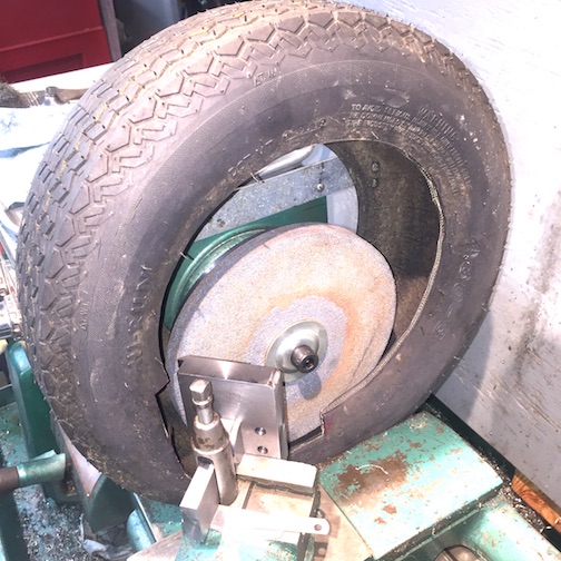
Last week I had to get it done. I finally assembled one from parts and pieces I had on hand. I had to buy a large nut and few bolts. There is still room for improvement but this got a set of blades sharpened and I am back to tree trimming and chipping. This is the result;
As always click on images to enlarge them
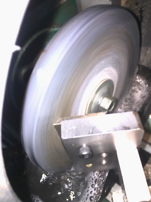
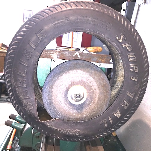
Figure - 01 and 01A final design
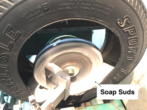
I discovered working on the last blade that a drop of Dawn dish soap in the water helps a lot. The soap makes the water wetter. It clings to the wheel better. After some suds develops that clings to the wheel and the blade. I also keeps the wheel cleaner, clears grindings away better, and actually cuts down on water splashing out of the tire. Keep in mind that if you use too much detergent, you will have too much suds. Fortunately I had my wet/dry shop vac close to suck up the extra suds.
Figure 1B with soap
The design evolution.
It took a bit of trial and error to get to this point. What follows is that process with the errors and discoveries I made along the way.
My shop is small and I don’t need this enough to warrant a dedicated machine. I had trouble convincing myself it would be ok to grind on my lathe. I decided it would be OK as long as I was able to control the grit. The solution was to grind wet, and risk getting some water on it, to avoid the grinding grit. Also a slow wet grind would protect the temper in the blades. I discovered it works best at about 150, not more than 200 RPM about 300 to 400 SFPM on the outer edge. I needed a good guard to surround the wheel to catch any water spray, grit, wheel fragments in case of a wheel breaking. I found an small trailer tire that had potential for a good guard and water catcher. I had anticipated glueing the wheel to a backing plate as mentioned by HMT member h7eh7e (I like to do bench grinders)
Figure - 02 first edition.
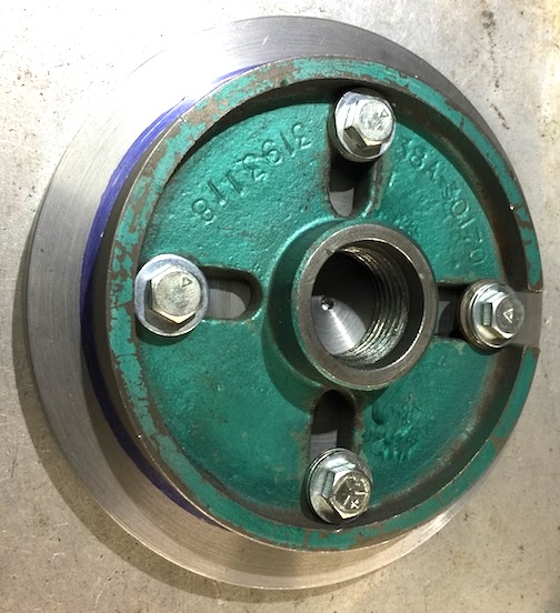
I already had a face plate with a larger steel plate that bolted on that I made for some another project. All I had to do was bore and tap a hole to bolt the grind wheel.
Figure - 03 and 03A Faceplate
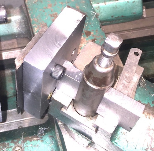
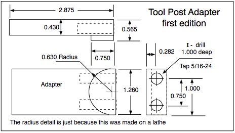
I made a blade holder to fit into my lantern tool post. My thought here was to keep the holder tight against the slide for rigidity and to set the angle with the slide.
Figure - 04 blade holder
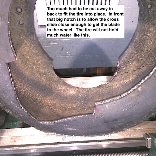
Then I cut the tire to fit around the spindle bearing housing and mounted it to the head stock cover. I had to cut away a lot of the tire side wall to fit around the spindle bearing. It was also necessary to cut away a lot in the front allow the blade and holder to reach the wheel
Figure - 05 first tire
At this point I had anticipated using a small pump to get water to the wheel, catch the run off in the tire and drain it back to a sump. But I was too excited to try it out. I poured some water into the tire, thinking the wheel would pick up some water as it rotated. However, I had to cut so much of the back sidewall out to fit the tire over the spindle bearing, most of the water ran out the back side of the tire.
But I DID try it anyway just to see how it worked. I just poured water onto the wheel from a bottle. The lathe was already wet, so what’s a little more water in the name of research.
The grinding went great. The faceplate was just too close to the head stock. There was no room for the tire. I need to get more clearance between the grinder and the head stock.
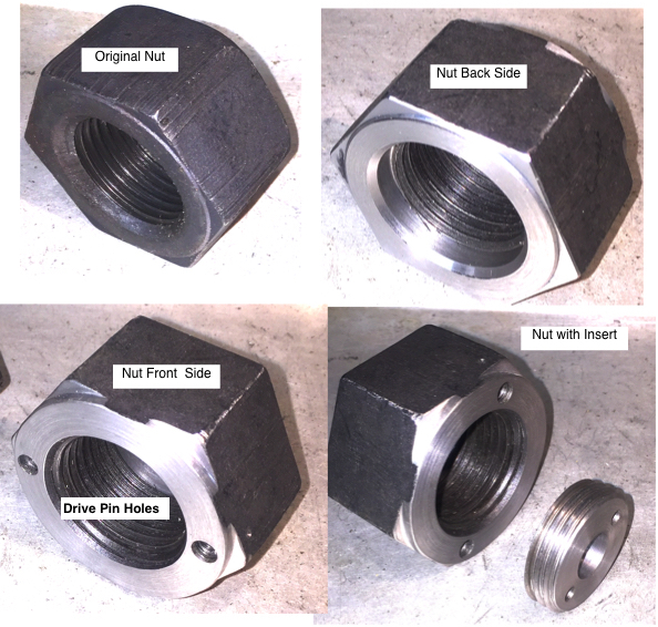
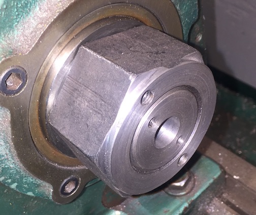
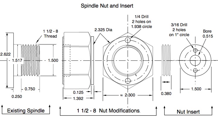
In order to avoid cutting so much of sidewall on the tire, I needed to get the wheel further from the head stock. Previously, I ordered a 1 1/2” - 8 heavy nut from McMaster-Carr to fit the spindle. It required some modifications to resister properly on the spindle each time it is installed. It also had to drive the backing plate and hold the wheel securely. I machined the nut and made a threaded insert to fit into the nut,
Figure - 06 spindle nut
Figure - 07 Nut Insert
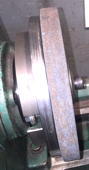
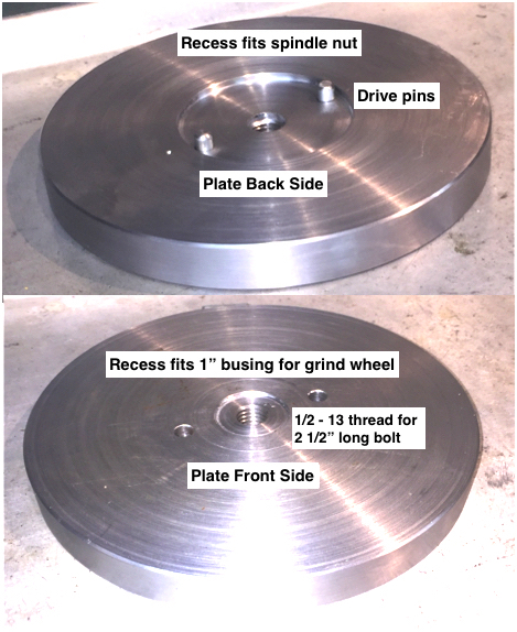
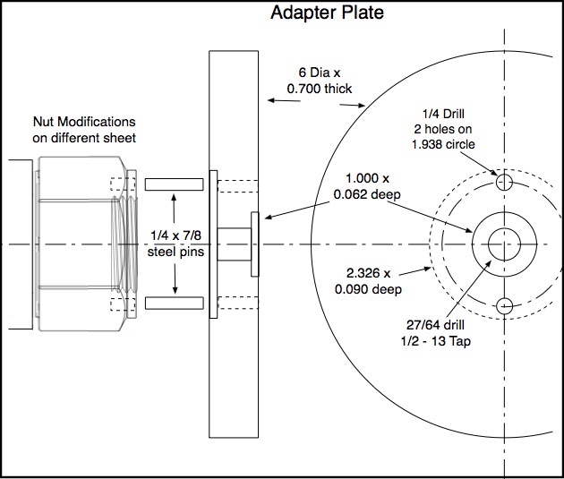
To mount the 8” wheel I made a 6” plate to fit the nut. As mentioned earlier, I had anticipated gluing the wheel to the plate. But this runs at low speed, only 150-200 RPM, I am confident if the wheel breaks the tire will contain the fragments. Above 200 RPM, about 400 SFPM, the wheel throws the water off. 150 RPM works very well.
Figure - 08 Adapter Plate
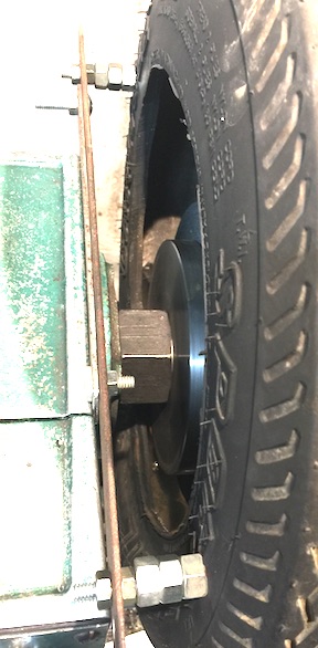
When assembled there is much more clearance behind the wheel for the tire to fit. On this tire, I only had to cut the wire beads off the tire, and make a small notch in front to clear the blade. MUCH more room to hold water.
Figure - 09 Tire Mounted
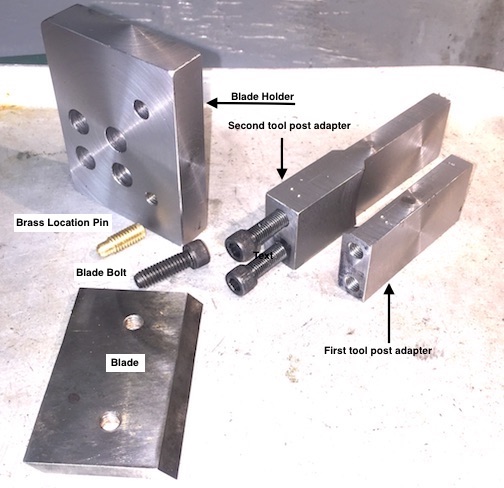
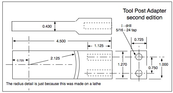
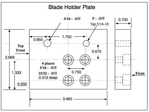
The holder fits my lantern tool post and sets on the top of the compound slide with no spacer. Initially the holder fit tight against the end of the compound slide. But that forced the cut out in the tire to be larger to allow the slide to actually fit into the tire. The second design is longer, and the blade holder is offset to allow the blade to contact the wheel while the compound slide remains outside the tire. The blade is secured with one socket head machine screw and a brass pin.
Figure -10 Blade holder
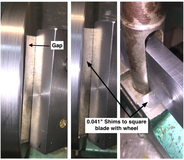
When I first mounted a blade in on the holder, I ran it up to the backing place to check alignment. I was very disappointed to discover the blade was not parallel to the face of the plate. It required 0.041” shims to align the blade with the plate.
Figure - 11 Tool Holder Shims
After discovering the miss alignment, I discovered that the top of my compound slide is not parallel with the axis of the spindle or perpendicular to the plate. I touched up the end of the tool post adapter with the wheel to make it perfectly aligned with the wheel. This helped, as I only needed 0.018 shims to correct the miss alignment. This led to the discovery that I drilled holes that attach the blade holder to the tool post adapter a little off. I also missed the alignment a little on the holes that hold the blade.
I think it is someone on HMT that has the signature line; “If you can’t make it perfect, make it adjustable!”
These are drawings of the Fabricated parts.
Figure 12-17
Typically blades are sharpened on both sides. In theory this allows the blades to be turned over and reinstalled with the new sharp edge exposed. However, in practice, the second edge is never as sharp as the first, because the edge is not protected. It is in the machine with all of the chips and dirt and dust. Then it is exposed to corrosion when not in use. The sharp edge is wasted before it does any real work. YES, it is better than the dull blade, but not as good as a freshly sharpened blade.
With two sets of blades, a sharp set is always available. If you wear both sets in the same day… you are working too hard, take a break!!!
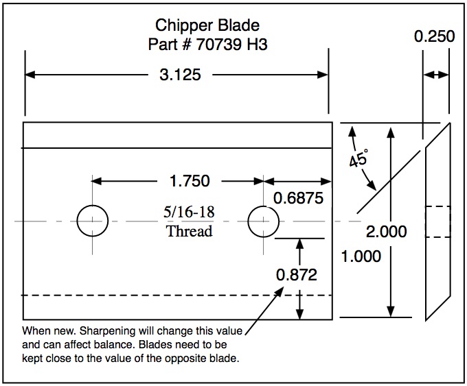
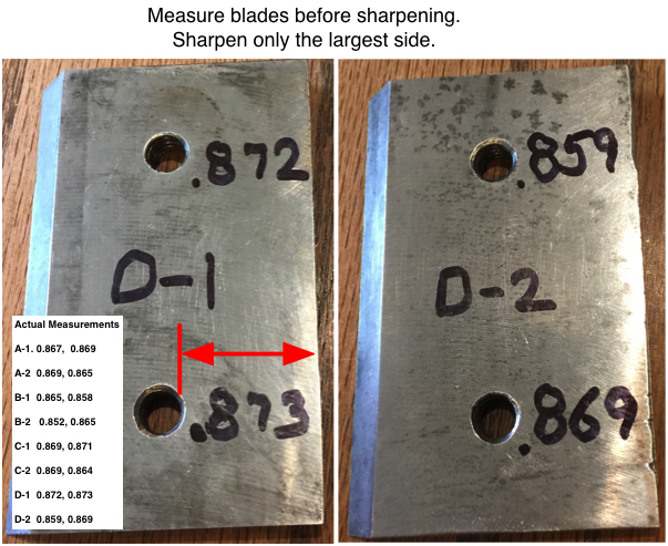
To maintain machine balance. Label each blade A1, A2, B1, etc.
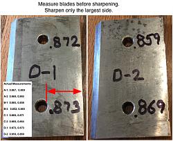
Measure the distance between each hole and and the sharp edge on each side. Only sharpen the largest side. When installing the blades, install the pairs closest in size across from each other. Notice in the following photo, one side on the blade has a sizable chunk missing. If that side of the blade is ground enough to remove that gash, the blade will be significantly lighter than the others. They do not have to be perfect. But if you always sharpen both sides each blade to get all of the nicks out, they will soon be different sizes. You can see from the chart in the photo, the largest variation between this 4 blade set is on one blade.
Figure 18 Measure Blades


 Reply With Quote

Bookmarks