Free 186 More Best Homemade Tools eBook:  
Get 2,000+ tool plans, full site access, and more.

User Tag List

Results 1 to 6 of 6

Thread: Made a wood lathe

  1. #1
    Ed
    Ed is offline
    Supporting Member
    Join Date
    Jun 2013
    Location
    Qld Australia
    Posts
    71
    Thanks
    9
    Thanked 44 Times in 28 Posts

    Ed's Tools

    Made a wood lathe

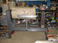
    This is my latest project which is a wood lathe/bowl turner.

    1. Bearing holder welded to a 10mm plate, the plate closest to the back of the lathe is larger than the front to be able to remove the face plate end bearing and shaft, pulleyed shaft and to fit the longer V-belts for changing pulley ratios, which will enable the lathe to reach a higher RPM in case I decide to turn something a bit smaller than the average size I intend to do. It's takes about 20min to change pulleys, bit of a pain to squeeze my arm down to the bottom of the headstock column and remove the bolts. The no load normal face plate RPM is 0-1160 and if I shift the motor back and align and use the smaller ratio pulleys, it reaches 0-2166 RPM. As I intend to do larger pieces for the majority of turning, I have reduced the ratio from the 1440RPM of the motor to get higher torque at slower shaft speeds. The motor is 4HP controlled by a Emheater 4Kw variable speed drive (VSD).
    2. Bearing fitted to the holder.
    3. Short legs I made to raise up the height of the lathe so that the center of the face plate is at a more comfortable height for turning.
    4. Capped the support SHS (Square Hollow Section) ends with a piece of plate which the wheels will attach to and make the lathe movable when required. As wood turning throws a lot of shavings and dust, I will move the lathe outside so that the shed remains wood free, As I mainly turn metal and weld in the shed, that will not end well if there is sawdust and wood shavings everywhere!
    5. Welded the modified Uni beams to the 4mm x 100mm SHS, the Uni beams were originally twice as high, but I plasma cut them down the middle and then switch welded the two halves together, this gave me the mass but without the height and the centre web is now about 20mm thick with 12mm tops and bottoms. I had originally intended to use those uni beams to make a large Hydraulic shop press, but after sitting in the shed for a few years I realized that I would get much more use out of a wood lathe then a big press, so they were reassigned. All up, the lathe completed should weigh about 350-400Kg.
    6 and 7. The motor mount rails are made from a piece of channel cut in half to make a piece of angle steel, the tops are 10mm and the support side is 8mm, each top has 4 holes drilled and tapped with a 9/16" thread to hold the motor down in two positions along the length. The motor can be positioned to move back for high speed and forward to get slower speed and more torque.
    8. Making the motor double pulley and drilling out the center with a 25mm drill. Finished the hole size with a boring bar to match the 28mm motor shaft, had to send it out to get a keyway broached as I don't have the broaching tools to do it myself. That is the only one of two things on this project that I couldn't do myself, the other being programming the VSD, had to get a sparky friend of mine to do that.
    9. Welded a piece of 10mm plate for webbing support for the front.
    Attached Thumbnails Attached Thumbnails Made a wood lathe-1.-welded-bearing-holder-plates-img_0595.jpg   Made a wood lathe-2.-6207-2rs-bearing-fitted-bearing-holder-img_0593.jpg   Made a wood lathe-3.-lathe-short-leg-img_0630.jpg   Made a wood lathe-4.-welded-plate-end-support-shs-img_0609.jpg   Made a wood lathe-5.-welded-uni-beams-support-shs-img_0614.jpg  

    Made a wood lathe-6.-motor-mount-support-rails-welded-img_0643.jpg   Made a wood lathe-7.-motor-support-rail-2-img_0639.jpg   Made a wood lathe-8.-making-motor-double-belt-pulley-img_0587.jpg   Made a wood lathe-9.-welded-front-support-img_0647.jpg  

    186 More Best Homemade Tools eBook

  2. The Following User Says Thank You to Ed For This Useful Post:

    kbalch (Oct 10, 2013)

  3. #2
    Ed
    Ed is offline
    Supporting Member
    Join Date
    Jun 2013
    Location
    Qld Australia
    Posts
    71
    Thanks
    9
    Thanked 44 Times in 28 Posts

    Ed's Tools
    10. and 11. Welded the two channels (300mm x 85mm), web support and motor support rails together.
    12.Assembled the spindle pieces together, the pulleys and spacers are welded to the main shaft. Fitted the face plate, (which has a 30mm x 3.5mm threaded boss welded to the stainless steel faceplate) and is screwed on to the threaded pulley shaft and locked in place with a 10mm grub screw and also a M14 socket cap bolt from the front. This will stop the face plate from unscrewing in the event I hit one of the 3 emergency stop buttons and the VFD brakes the work piece quickly. Then machined the lot to make sure that it was all true and that the bearings will fit on it.
    13. Made a bracket to hold the motor, 10mm thick and cut the hole with a plasma cutter. 4 x 9/16" bolts hold the motor to it.
    14. Tool rest column is a piece of 10mm thick tube which was rusty and pitted on the inside, so had to make a long boring bar out of a 400mm x 19mm stainless rod fitted it with a TPMG 434 ceramic insert to turn the insides down to 8mm, a lot of chatter but it did an acceptable job. Put in 5 slots at the top with a thin cut off disk. The round solid rod is a piece of 60mm which I turned down to 55mm to fit the tube and the ring clamp is from a turned piece of thicker steel round bar with two lugs welded to it and a 9/16" bolt though them which clamps the tube against the tool post and holds the tool post in it's position. It's held around the tube with a 30mm long weld on the top and bottom at one end, leaving the rest of it to squash the slots against the post locking it in place.
    15. The sliding part of the tool post setup is a piece of 50mm machined solid square steel, it is overkill but it was the only thing suitable that I had lying around and couldn't think of any other use that I could use it for at the time. It slides within a piece of 6mm thick channel made from a cut down and reshaped piece of 75mm SHS, welded down onto to a 16mm thick X 150mm wide scrap piece of flat bar base. A 3/4" bolt holds the sliding bar in place and another locks the whole tool rest post setup down to the Uni beam frame.
    16. and 17. Weld holding the post column to the sliding arm.
    18. Welded frame ready for painting with a charcoal coloured Hammer tone paint.
    19. and 20. Painted, the top bar of the the tool rest is from a piece of left over truck spring welded on an angle to the post, I had cut the ends off it previously to make the turning chisels.
    Attached Thumbnails Attached Thumbnails Made a wood lathe-11.-two-channels-front-support-web-motor-rails-welded-2-img_0650.jpg   Made a wood lathe-12.-trueing-up-entire-shaft-pulleys-img_0588.jpg   Made a wood lathe-13.-made-painted-motor-mount-frame-img_0636.jpg   Made a wood lathe-14.-tool-rest-support-columm-ring-clamp-img_0666.jpg   Made a wood lathe-15.-tool-rest-column-slide-img_0674.jpg  

    Made a wood lathe-16.-tool-rest-column-slide-welded-img_0672.jpg   Made a wood lathe-17.-tool-rest-slide-column-welded-2-img_0671.jpg   Made a wood lathe-18.-welded-frame-ready-painting-img_0658.jpg   Made a wood lathe-19.-assembled-painted-img_0676.jpg   Made a wood lathe-20.-assembled-painted-2-img_0677.jpg  


    2000 Tool Plans

  4. #3
    Ed
    Ed is offline
    Supporting Member
    Join Date
    Jun 2013
    Location
    Qld Australia
    Posts
    71
    Thanks
    9
    Thanked 44 Times in 28 Posts

    Ed's Tools
    21. The back of the lathe where the motor sits, the end of the shaft has another 30mm x 3.5mm thread where I will put a round disk handle to help with spinning on the faceplate and work piece as well a some sort of locking device. It also shows the larger size bearing support plate which I can remove the bearing for changing V-Belts and to remove the pulleyed shaft if necessary.
    22. Machined and drilled stainless steel face plate, machined down to 10mm thick which should be strong enough. This lathe will be able to swing a log of about 1m wide and 1m long
    23. The top of the lathe head showing the insides and where a metal cover will go over it to enclose it all.
    24 & 24a Made a couple of Idler rollers to tension up the belts, a bit of stainless tubing bored out at each end to fit a small ball bearing and a bolt to connect it all together, slots cut into the motor frame to allow individual tension adjusting.
    25. Need an extra plate to make the fan holder end, didn't have the right size plate so found two triangular 4mm off cuts and tacked them together. Then cut out the fan hole with the plasma cutter.
    26. Plate after welding.
    27. Motor cover tacked up ready for welding.
    28. Motor cover welded up
    29. Fan installed to motor cover and fitted.
    Attached Thumbnails Attached Thumbnails Made a wood lathe-21.-lathe-back-larger-bearing-support-plate-img_0664.jpg   Made a wood lathe-22.-machined-10mm-thick-drilled-stainless-face-plate-img_0661.jpg   Made a wood lathe-23.-fitted-shaft-2-ratio-pulleys-bearings-supports-face-plate-fitted-img_0663.jpg   Made a wood lathe-24.-idler-tensioners-img_0679.jpg   Made a wood lathe-24a.-idlers-fitted-img_0680.jpg  

    Made a wood lathe-25.-joining-two-triangle-plates-fan-support-1-img_0694.jpg   Made a wood lathe-26.-fan-plates-welded-img_0702.jpg   Made a wood lathe-27.-motor-cover-tacked-up-welding-hole-cut-out-fan-img_0703.jpg   Made a wood lathe-28.-motor-cover-welded-up-img_0706.jpg   Made a wood lathe-29.-fan-installed-motor-cover-img_0708.jpg  


  5. #4
    Ed
    Ed is offline
    Supporting Member
    Join Date
    Jun 2013
    Location
    Qld Australia
    Posts
    71
    Thanks
    9
    Thanked 44 Times in 28 Posts

    Ed's Tools
    30. Electronic fan control fitted to cover, set to switch the fan on when the motor gets to 50 C and switches the fan off when motor drops back to 35 C, plus fuse, power switch and an emergency stop switch which connects to the control panel.
    31. Pipe welded to baseplate to hold the remote control panel, it gets screwed down to a piece of 600mm square ply.
    32. Completed remote control panel, containing the Variable Speed Drive (VSD) emergency stop button, main switch and a 10amp 3 phase circuit breaker. Most of the 3 phase sockets in my shed are either 32amp or 40amp and protected by the same circuit sized breakers, so this enables me to connect it to any of them and still be protected by the 10amp breaker on the panel for the motor.
    33. Welded a 30mm x 3.5mm nut I made inside a 8mm x 60mm pipe for the tool post holder. This becomes part of the sleeve for sliding the threaded MT3 holder in and out.
    34. Tool post holder and sleeve.
    35. Welded two parallel C channels (230mm x 75mm) together for the post frame and cut out a hole for the sleeve.
    36. Welded frame to 10mm base plate
    37. Tool post mostly assembled
    38. Tool post handle with stainless tube handle sleeve.
    39. Tool post locking nut.
    Attached Thumbnails Attached Thumbnails Made a wood lathe-30.-electronic-temp-control-fitted-motor-cover-img_0715.jpg   Made a wood lathe-31.-pipe-welded-baseplate-control-panel-.jpg   Made a wood lathe-32.-completed-control-panel.jpg   Made a wood lathe-33.-welded-30mm-nut-inside-tool-post-sleeve-img_0721.jpg   Made a wood lathe-34.-mt3-tool-holder-sleeve-img_0716.jpg  

    Made a wood lathe-35.-welded-2-parallel-channels-tool-post-frame-img_0722.jpg   Made a wood lathe-36.-welded-tool-post-frame-baseplate-img_0727.jpg   Made a wood lathe-37.-tool-post-mostly-assembled-img_0734.jpg   Made a wood lathe-38.-tool-post-handle-img_0733.jpg   Made a wood lathe-39.-toolpost-handle-locking-nut-img_0743.jpg  


  6. #5
    Ed
    Ed is offline
    Supporting Member
    Join Date
    Jun 2013
    Location
    Qld Australia
    Posts
    71
    Thanks
    9
    Thanked 44 Times in 28 Posts

    Ed's Tools
    40. Completed tool post
    41. Was anxious to test it out so that I could try out the controls, found a rubber tree locally that was cut down and was destined to be burnt off, so got a few logs from it. Even though it was severely out of balance I didn't get any vibration in the lathe up to several hundred RPM, couldn't test faster as the wood was green and it is a very soft wood, even surprisingly so, being out of balance was causing the tailstock live center to gouge out of the end as well as the screws holding the log to the faceplate to pull out. Later on I ended up throwing all the rubber tree logs on the woodpile to get burnt off, I have much better wood now which doesn't give me any trouble.

    Still have a few things to do and adjust, the VSD needs to be reprogramed to apply more power for the motor braking so that it will slow down much faster on larger logs as well as boosting the power for the low rev range. My 2 pulley speeds with the VSD give me a 0-1160 and 0-2166 RPM no load range but I will use the lower range mostly due to the size of logs I intend to spin. I should be able to swing a 1m wide log on it but will also have to add a winch to this setup as it was very hard just to put this size of log on it. Still have to build a small locking device at the motor end to lock the spindle shaft when required. Still waiting on another emergency stop switch so that I can switch it off at the tail stock end, that way I can switch it off at either end of the lathe and also at the control panel without having to cross the spinning wood in the middle. Apart from that, it ran better than I expected it to. Currently looking for a small wood lathe chuck to grab the wood at the headstock end better, currently using 10 x 10mm x 40mm coach screws which means there is a fair bit of wastage when I go to cut the bowl off.

    Also need to add another 3 phase plug and socket between the control panel and the lathe, so that I can disconnect the control panel from the lathe and then use it to control a 12" 3 phase table saw which is my next project...


    Ah!! so many projects and so little time to do them!!


    Cheers

    Ed.
    Attached Thumbnails Attached Thumbnails Made a wood lathe-40.-toolpost-live-center-img_0744.jpg   Made a wood lathe-41.-testing-out-rubber-tree-logimg_0737.jpg  

  7. The Following User Says Thank You to Ed For This Useful Post:

    rendoman (Nov 11, 2019)

  8. #6
    kbalch's Avatar
    Join Date
    Jun 2012
    Location
    Clermont, FL
    Posts
    5,034
    Thanks
    2,275
    Thanked 531 Times in 383 Posts
    Thanks Ed.! Very nice work. I've added your Wood Lathe to our Metalworking and Electrical categories, as well as to your builder page: Ed.'s Homemade Tools. Your receipt:


    186 More Best Homemade Tools eBook

Thread Information

Users Browsing this Thread

There are currently 1 users browsing this thread. (0 members and 1 guests)

Bookmarks

Posting Permissions

  • You may not post new threads
  • You may not post replies
  • You may not post attachments
  • You may not edit your posts
  •