Free 186 More Best Homemade Tools eBook:  
New: 300+ fresh build posts/day from 275 forums → BuildThreads.com

User Tag List

Results 1 to 6 of 6

Thread: Mini Mill - DIY Milling Machine

Threaded View

  1. #1
    Supporting Member cagiva's Avatar
    Join Date
    Apr 2021
    Posts
    4
    Thanks
    60
    Thanked 9 Times in 1 Post

    cagiva's Tools

    Mini Mill - DIY Milling Machine

    Scratch built table top mini mill made from common materials. Simple to construct without the complications of specialised tooling being needed. It is possible to make and assemble this machine using only basic hand tools and a drilling machine.


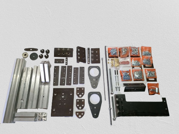
    • 1 meter (3.2 Feet) or less of Aluminium Profile
    • A single 300x300 MM sheet of Material is sufficient for the entire build
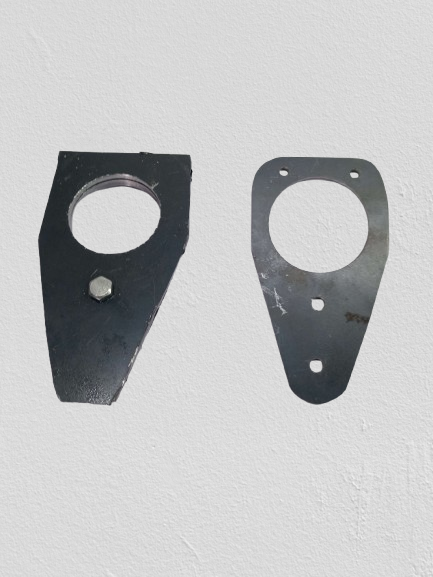
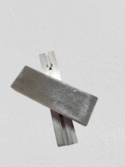
    • The flat and square bar seen was used for convenience. The parts could arguably be derived from the same material as the machine sides
    • Tapped holes are not strictly necessary
    • Base plate is salvaged mild steel 130MMx120MMx8MM


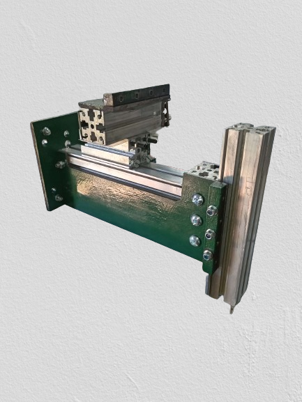
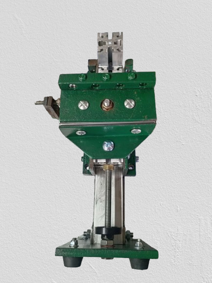
    Took about 6 hours to put together. Quite a fun little build and the machine capabilities blew me away a bit, wasn't expecting much but am now impressed after some tests. The aluminium extrusion is 35x35 MM with 6 MM T Slots, I recon PG40x40 Heavy will work as well (10 MM T Slot).

    Name:  IMG_20241007_190649_edit_81407657292312-removebg-preview.png
Views: 2781
Size:  127.8 KB

    The sheet of clear plastic is a chip guard that slots into the table.

    Click image for larger version. 

Name:	iso view image.png 
Views:	322 
Size:	320.5 KB 
ID:	48103Click image for larger version. 

Name:	front view.png 
Views:	231 
Size:	263.9 KB 
ID:	48104Click image for larger version. 

Name:	side view.png 
Views:	252 
Size:	289.9 KB 
ID:	48105
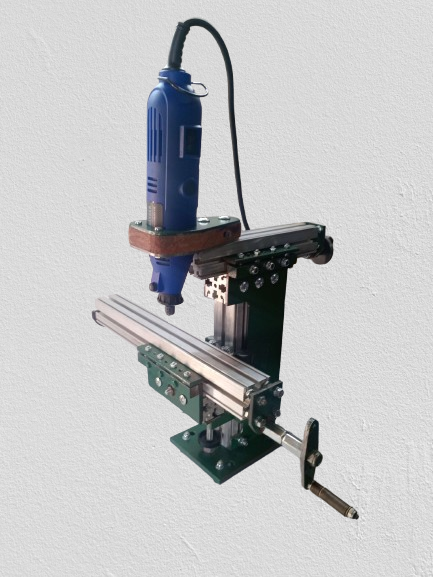
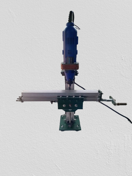
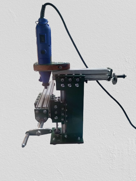
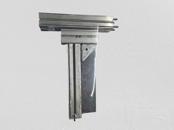
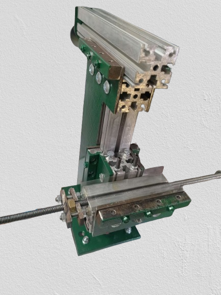
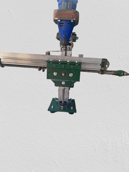
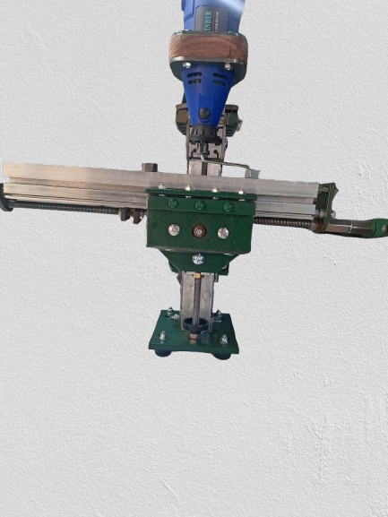
    Three views with Rotary Tool Spindle fitted
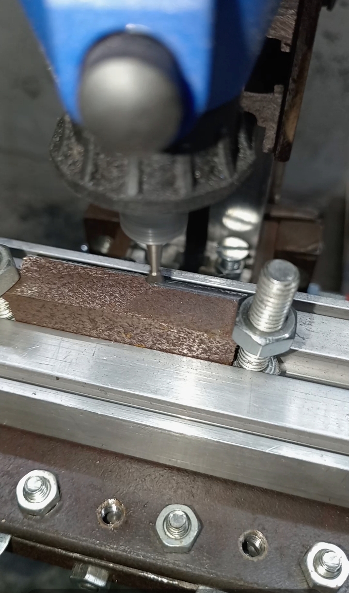
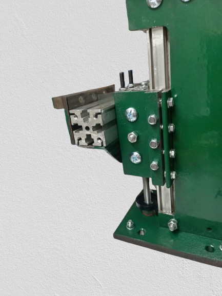
    The Z axis is a bolt and brass nut combo. The knee is drilled about 80% through to accommodate the screw.

    Click image for larger version. 

Name:	IMG_20241007_193940.jpg 
Views:	275 
Size:	868.9 KB 
ID:	48106Click image for larger version. 

Name:	IMG_20241007_193826.jpg 
Views:	238 
Size:	1.15 MB 
ID:	48107Click image for larger version. 

Name:	IMG_20241007_185744_edit_81587411391784-removebg-preview.png 
Views:	263 
Size:	353.8 KB 
ID:	48108
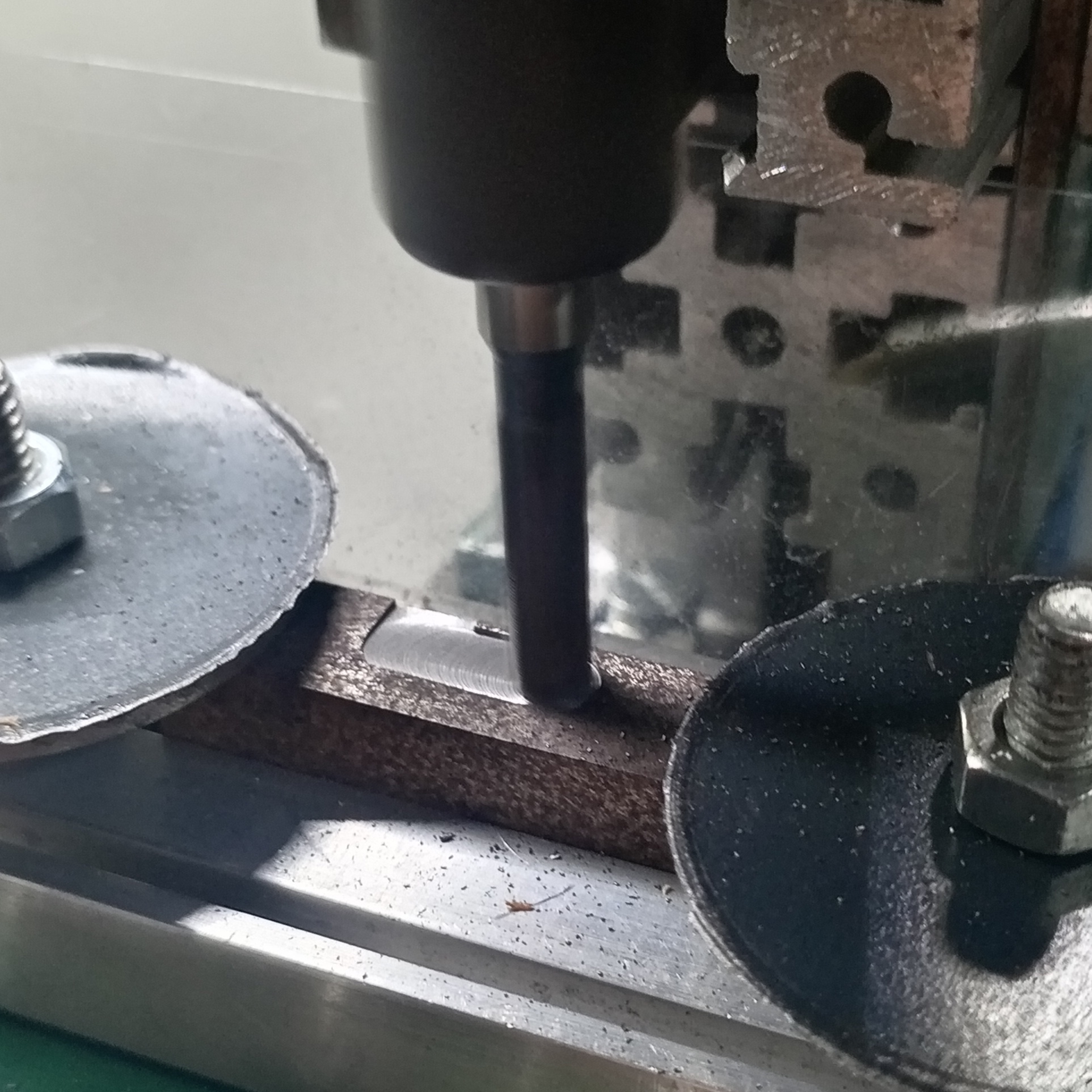
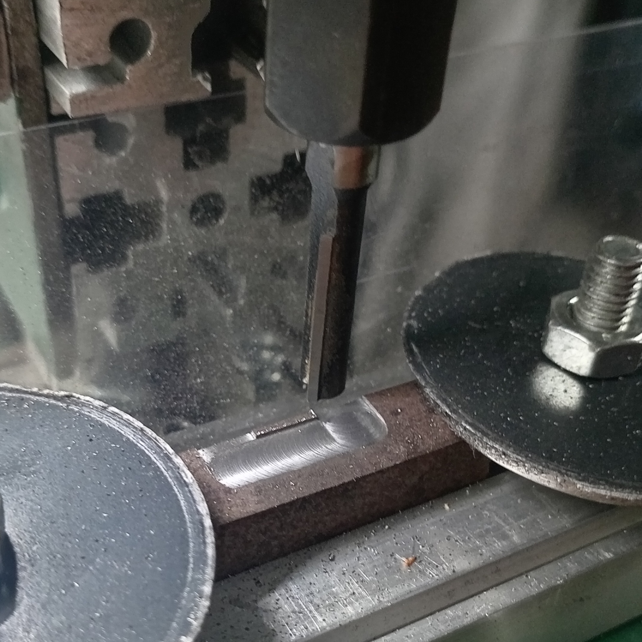
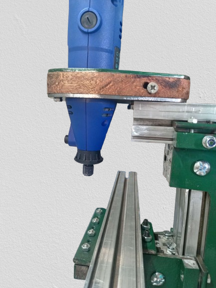
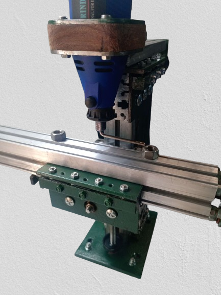
    Close Up Milling Action.
    Tested climb milling, plunging and slot milling without any drama. One notable issue is the lack of machine dampening, although rigid with little to no chatter. from what I can tell, at higher spindle speeds vibrations tend to wiggle things loose.

    Click image for larger version. 

Name:	Screenshot_20241007_135900_com.hihonor.photos.jpg 
Views:	210 
Size:	491.8 KB 
ID:	48109Click image for larger version. 

Name:	IMG_20241007_190423_edit_81542745923166.jpg 
Views:	230 
Size:	1.44 MB 
ID:	48110Click image for larger version. 

Name:	IMG_20241007_190507_edit_81524518393549.jpg 
Views:	218 
Size:	1.23 MB 
ID:	48111
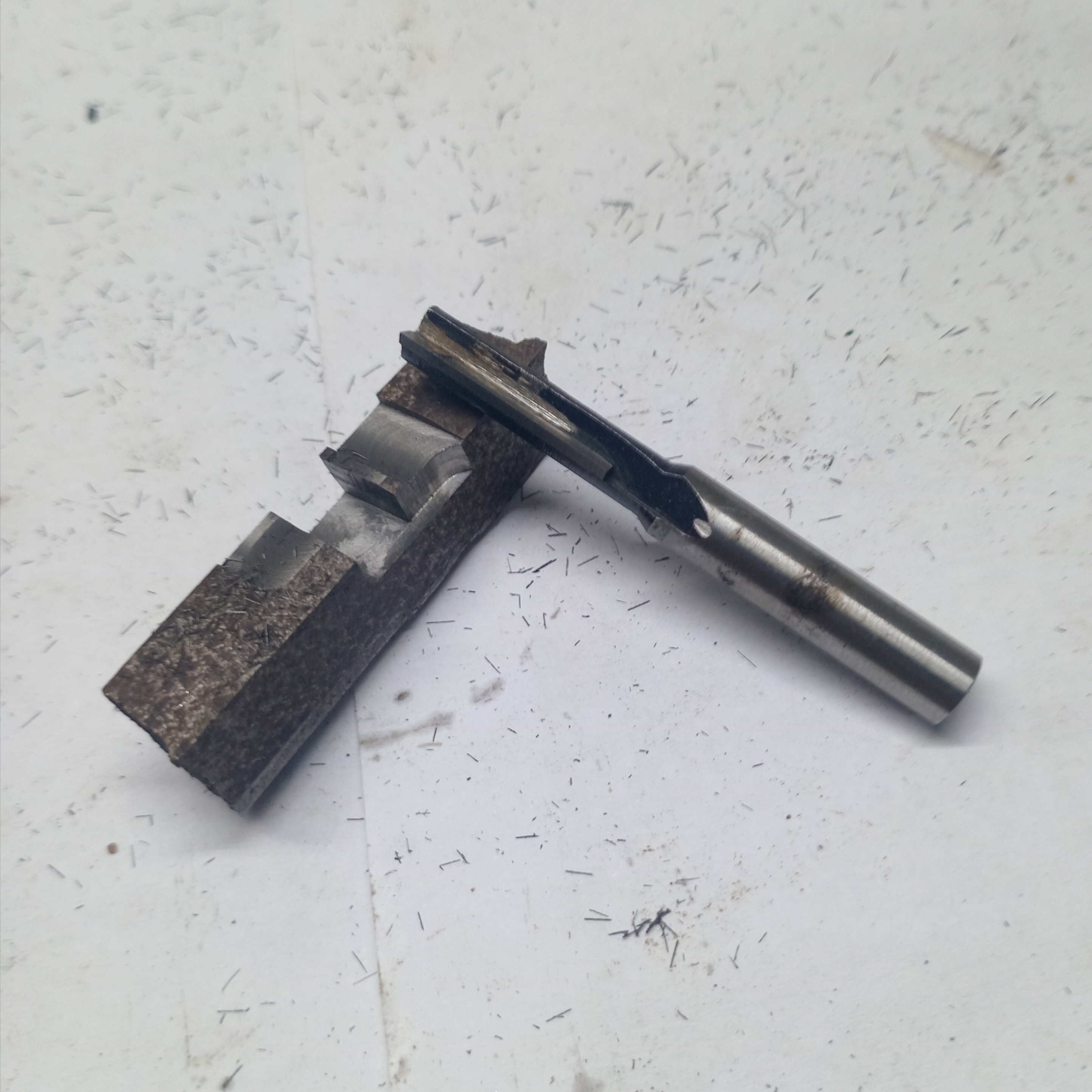
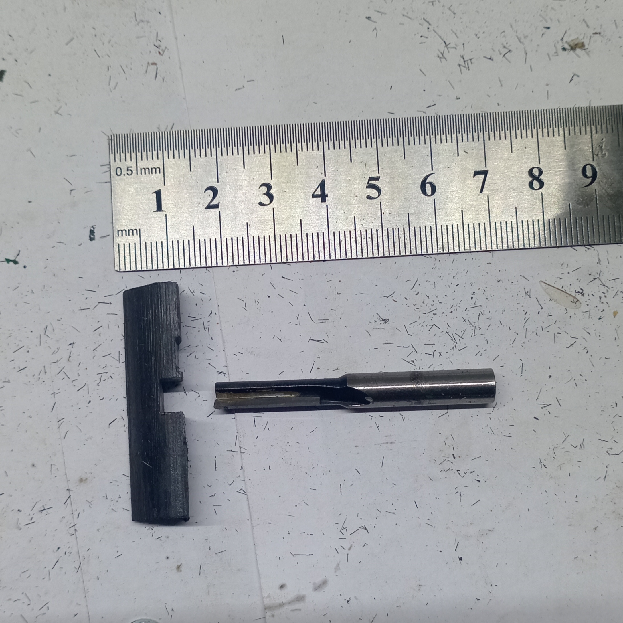
    6 MM 2 Flute Carbide Cutter (Straight Flute) in cast iron plus micro milling with 3 MM HSS dovetail cutter
    Cutting parameters: 0.4 - 4 MM depth of cut. 18000-25000 RPM @ 100-200 MM/MIN full cutter width
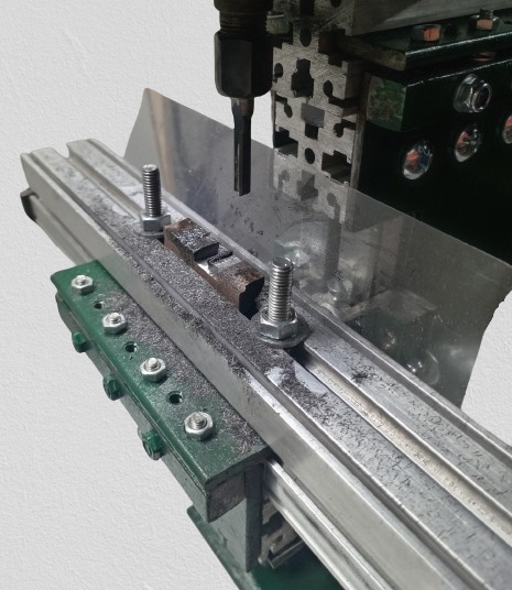
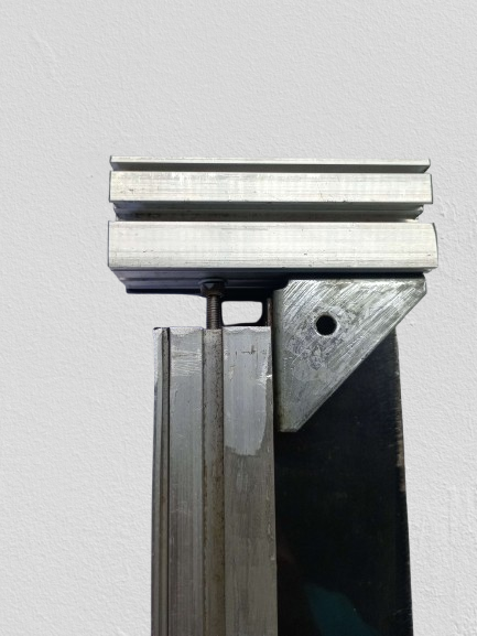
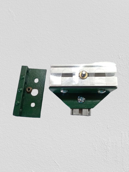
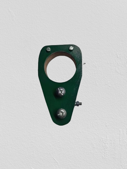
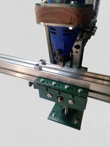
    The threaded holes are for set screws and would be used to level the gibb and remove slop. The holes should have been drilled closer to the operator (offset from the through hole axis'). I had to use thick shims without set screws to achieve the desired results.

    Click image for larger version. 

Name:	IMG_20241004_144819-removebg-preview (1).png 
Views:	290 
Size:	363.9 KB 
ID:	48101Click image for larger version. 

Name:	IMG_20241005_095832-removebg-preview.png 
Views:	229 
Size:	289.3 KB 
ID:	48112Click image for larger version. 

Name:	IMG_20241005_103652-removebg-preview.png 
Views:	224 
Size:	284.7 KB 
ID:	48113Click image for larger version. 

Name:	IMG_20241005_120540-removebg-preview.png 
Views:	232 
Size:	304.0 KB 
ID:	48114
    Click image for larger version. 

Name:	IMG_20241005_115906-removebg-preview.png 
Views:	230 
Size:	283.2 KB 
ID:	48115Click image for larger version. 

Name:	IMG_20241005_145810-removebg-preview.png 
Views:	243 
Size:	328.7 KB 
ID:	48116Click image for larger version. 

Name:	IMG_20241005_153631-removebg-preview.png 
Views:	344 
Size:	343.8 KB 
ID:	48117
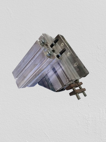
    To avoid drilling into faces of the extrusion I opted to run an M5 rod through the centre and bolt the ram guide block and base plate together through the column. I tested the unit without this rod and it works just fine. Obviously the tool ends up less ridged but it didn't seem terrible.

    Click image for larger version. 

Name:	IMG_20241005_114128-removebg-preview.png 
Views:	202 
Size:	277.4 KB 
ID:	48118Click image for larger version. 

Name:	IMG_20240928_142528-removebg-preview.png 
Views:	213 
Size:	250.4 KB 
ID:	48119Click image for larger version. 

Name:	IMG_20241004_221438-removebg-preview.png 
Views:	213 
Size:	251.9 KB 
ID:	48120Click image for larger version. 

Name:	IMG_20241005_142939-removebg-preview.png 
Views:	263 
Size:	323.1 KB 
ID:	48121
    Click image for larger version. 

Name:	IMG_20241005_164001-removebg-preview.png 
Views:	219 
Size:	374.8 KB 
ID:	48122Click image for larger version. 

Name:	IMG_20241005_101655-removebg-preview.png 
Views:	205 
Size:	261.3 KB 
ID:	48123Click image for larger version. 

Name:	IMG_20241005_152649-removebg-preview.png 
Views:	318 
Size:	345.8 KB 
ID:	48124
    Metal-on-metal contact is avoided by using book biding cover plastic cut outs with slits cut in them to trap oil. These cut outs are sandwiched between sliding surfaces.
    This same plastic is also used as shim stock when required. I'm sure its not the best all round material but it certainly does the trick and costs pennies a sheet at any stationary shop. I may also like to try gasket paper perhaps.
    All faces of the aluminium extrusions were honed to remove burs and other surface defects.

    Click image for larger version. 

Name:	IMG_20241005_164929-removebg-preview.png 
Views:	217 
Size:	301.4 KB 
ID:	48125Click image for larger version. 

Name:	IMG_20241005_164944-removebg-preview.png 
Views:	219 
Size:	304.5 KB 
ID:	48126Click image for larger version. 

Name:	IMG_20241005_165045-removebg-preview.png 
Views:	202 
Size:	346.9 KB 
ID:	48127Click image for larger version. 

Name:	IMG_20241005_165323-removebg-preview.png 
Views:	233 
Size:	327.1 KB 
ID:	48128Click image for larger version. 

Name:	IMG_20241005_165404-removebg-preview.png 
Views:	288 
Size:	335.0 KB 
ID:	48129
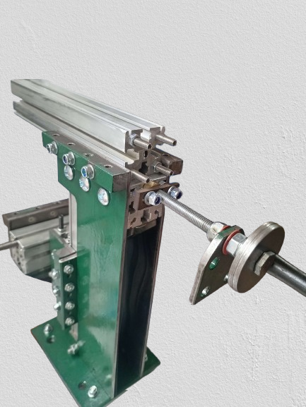
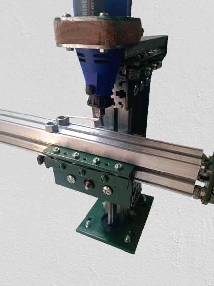
    Low-tech table alignment. A flex shaft spindle tommy bar is colleted and the long end swept over four points on the table. First the table is made perpendicular to the spindle at the front side. The table guide block has two bolts connected to the knee. the upper bolt is the pivot point and the lower to lock it. Both bolts are torqued when the the wiper gap is equal across both points. The ram is traversed back and the distances checked as pictured to ensure parallelism with the table (if not, the machine is reassembled with special care given to making the column and ram block meet at 90 degrees) the table 'level' is then checked a second time from the back.

    Would love to hear any thoughts and suggestions thanks,
    Cheers.
    Last edited by cagiva; Oct 7, 2024 at 06:56 PM.
    Best,
    D.S. [cagiva]

  2. The Following 9 Users Say Thank You to cagiva For This Useful Post:

    bruce.desertrat (Oct 14, 2024), DSTP (Oct 8, 2024), emu roo (Oct 8, 2024), guitwar (Nov 16, 2024), Jon (Oct 7, 2024), Ralphxyz (Oct 12, 2024), rdarrylb (Oct 8, 2024), that_other_guy (Oct 8, 2024), tuchie (Oct 12, 2024)

Thread Information

Users Browsing this Thread

There are currently 1 users browsing this thread. (0 members and 1 guests)

Tags for this Thread

Bookmarks

Posting Permissions

  • You may not post new threads
  • You may not post replies
  • You may not post attachments
  • You may not edit your posts
  •