 LinkBack URL
 About LinkBacks
Short preview for the whole system.
Hi
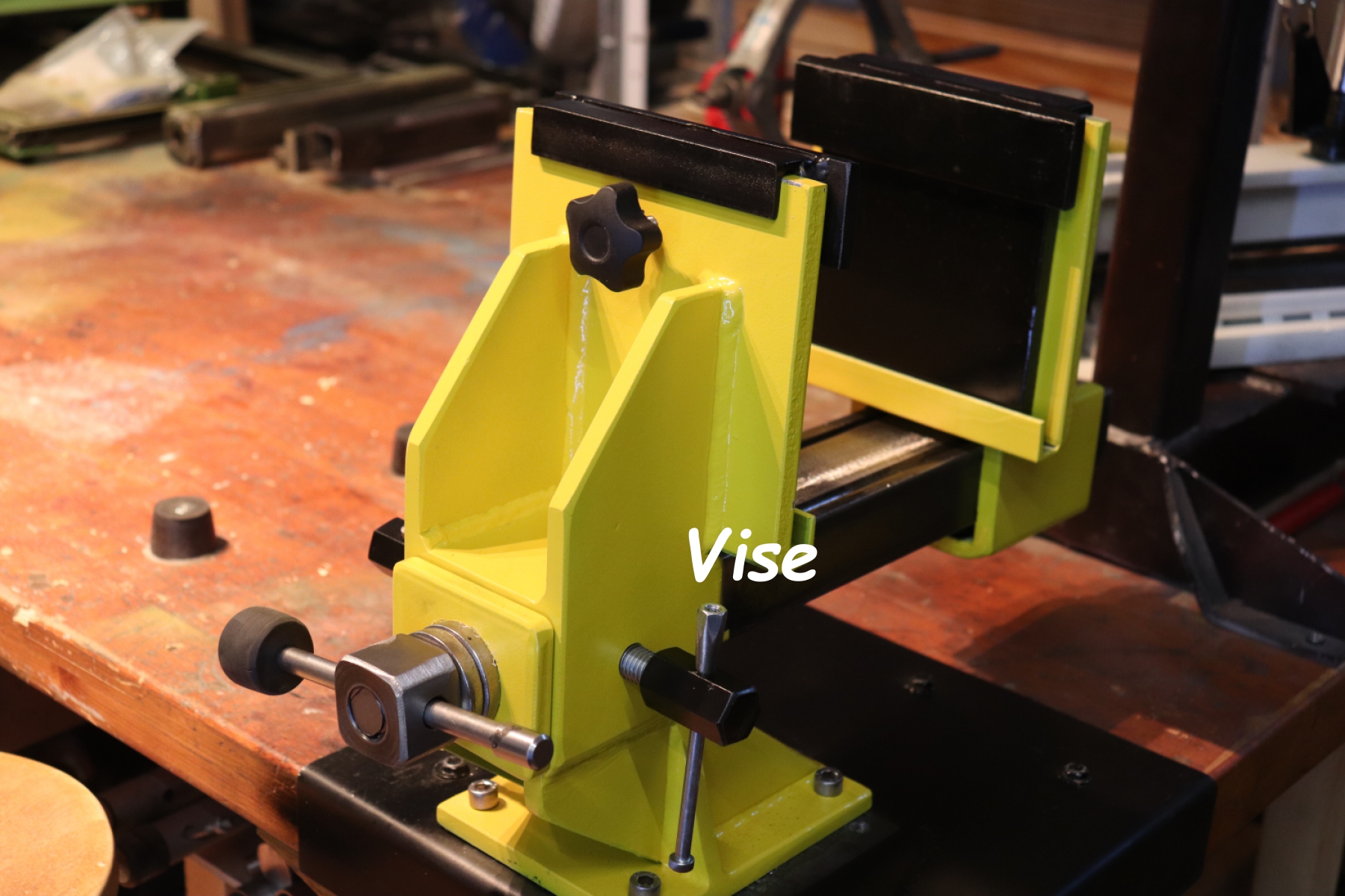
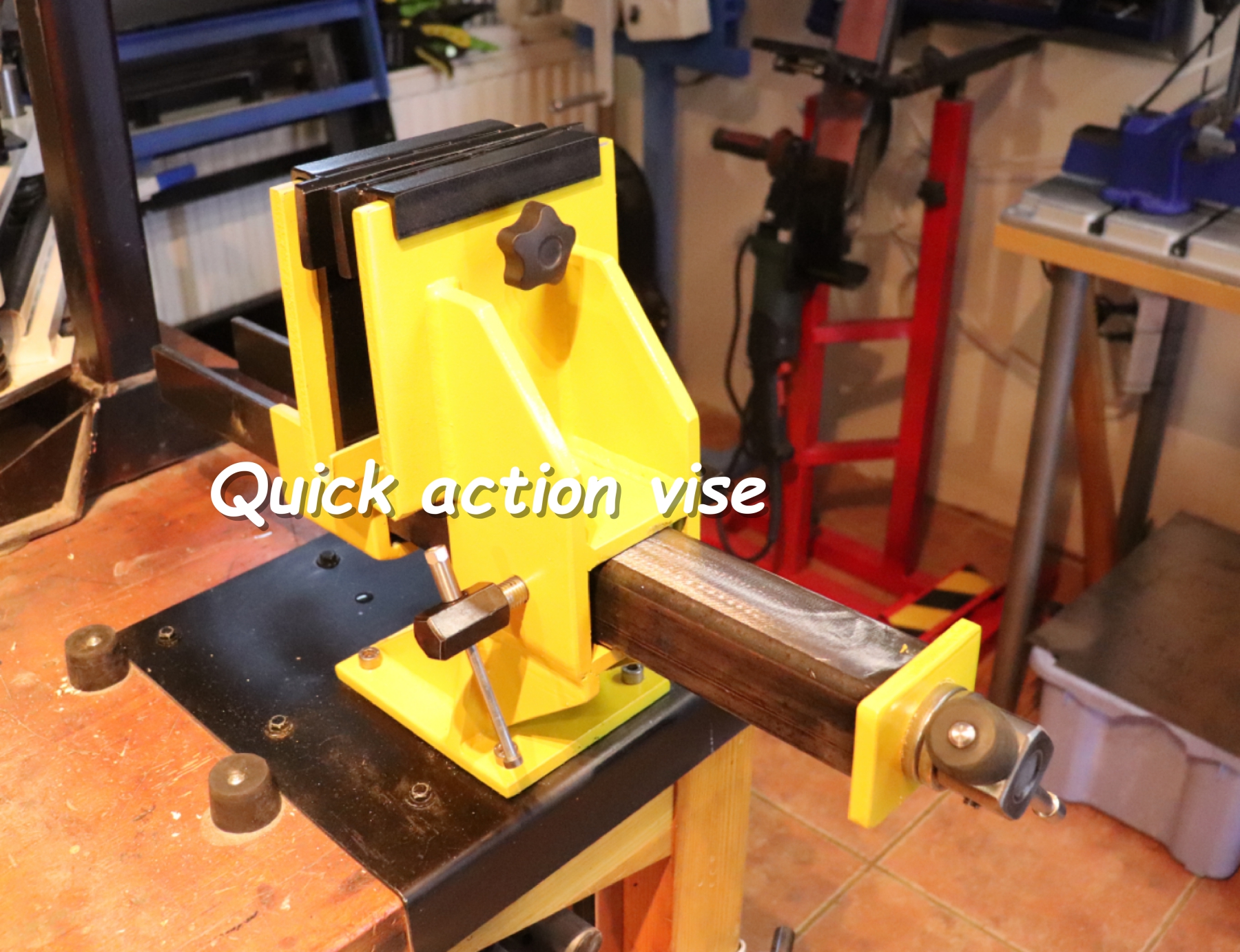
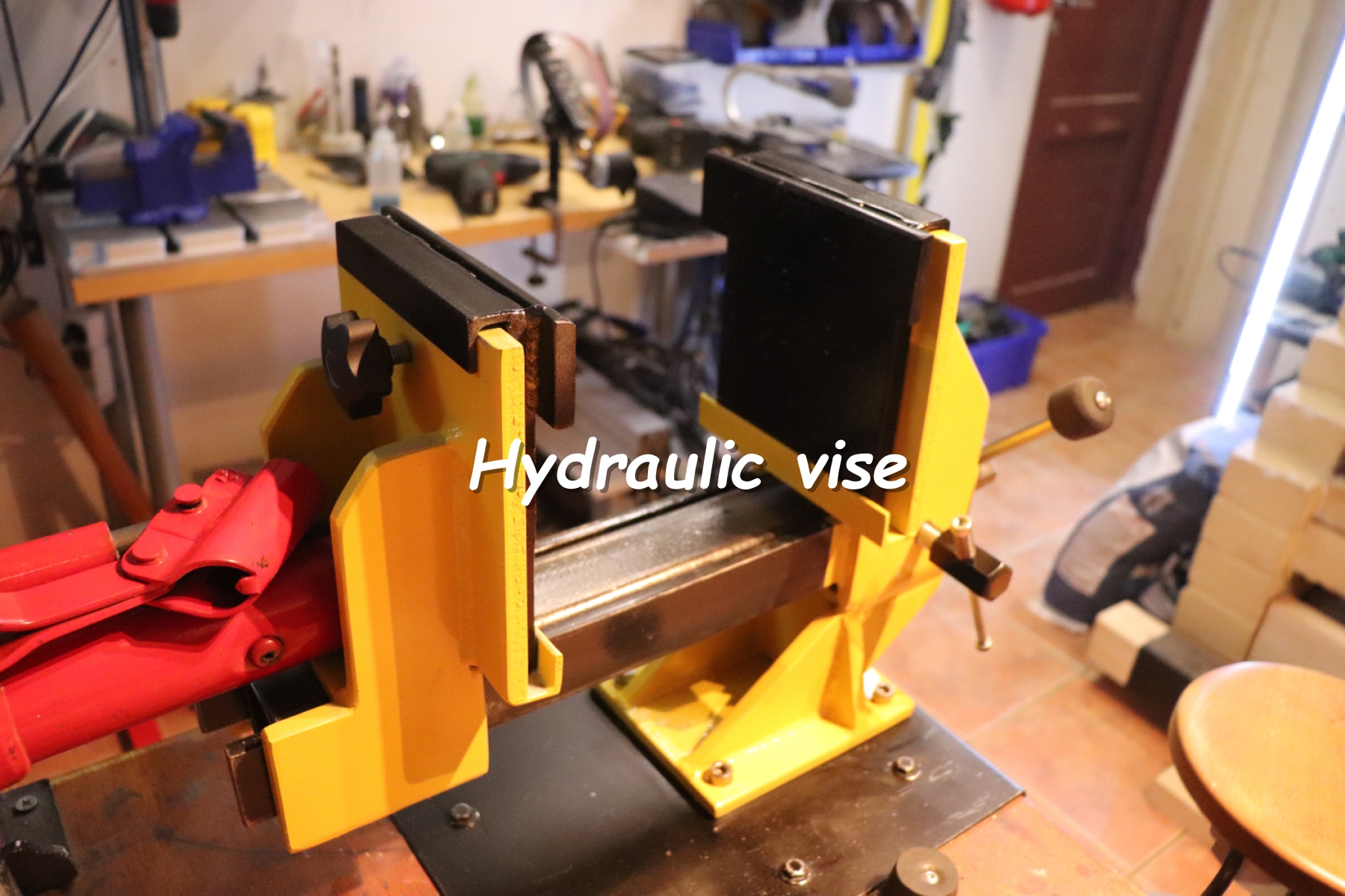
I have been planning "Multipurpose vise" for a while.
Here it is:
Edit:
Making the adds:


Short preview for the whole system.
Hi
I have been planning "Multipurpose vise" for a while.
Here it is:
Edit:
Making the adds:
Last edited by Tuomas; Nov 30, 2019 at 12:10 AM.
Canyonman44 (Feb 13, 2024), Clockguy (Nov 11, 2019), Corm (Nov 11, 2019), dekeros (Nov 9, 2019), digout (Dec 25, 2019), Drew1966 (Nov 15, 2019), emu roo (Mar 11, 2026), IAMSatisfied (Nov 11, 2019), Inner (Nov 15, 2019), Janvosburg (Feb 13, 2024), Jon (Nov 9, 2019), kess (Nov 11, 2019), KustomsbyKent (Mar 4, 2024), LMMasterMariner (Nov 10, 2019), nova_robotics (Feb 13, 2024), PowerMk (Nov 11, 2019), Ralphxyz (Feb 14, 2024), Scotty12 (Nov 11, 2019), tekcraft (Nov 12, 2019), thehomeengineer (Nov 16, 2019), Tule (Nov 12, 2019)
There are currently 1 users browsing this thread. (0 members and 1 guests)
 Posting Permissions


 Reply With Quote
Bookmarks