
 LinkBack URL
 About LinkBacks


Hi All
I have started on the rewire of my 4x6 bandsaw. There are a couple of reasons for the rewire first the saw is 35+ years old secondary I want to incorporate a coolant system on the saw and thirdly the current on/off switch is not suitable for for a coolant system.
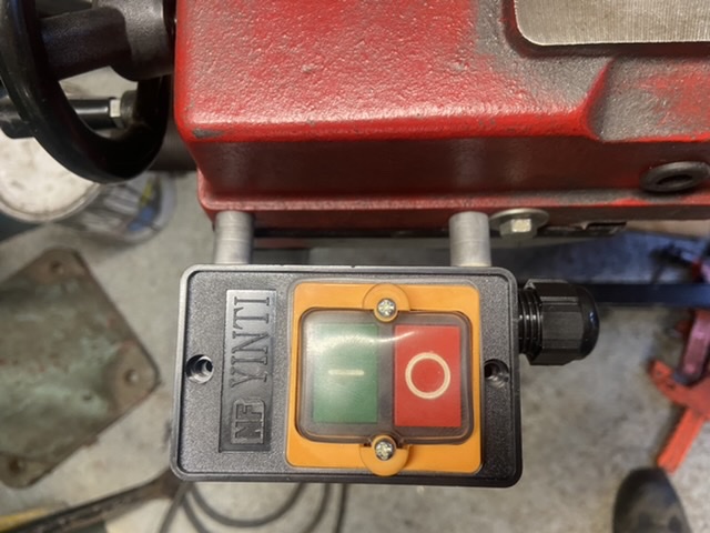
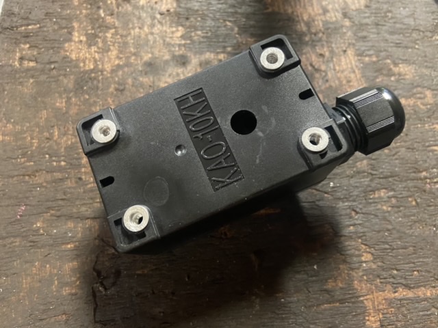
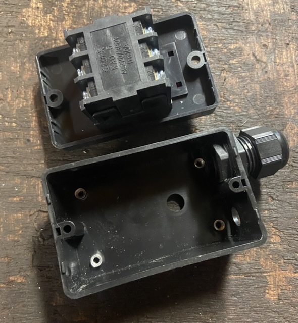
The old switch is not waterproof and at the moment fits directly under the saw frame. A new waterproof switch was purchased or advertised as a waterproof switch. The switch itself is probably waterproof but the terminal box definitely isnt. The switch needs to be moved and requires a new mounting bracket. This will be fabricated with two stand-offs so coolant can return to the reservoir and not pool on a sheet metal bracket bolted directly into side of the base of the saw.
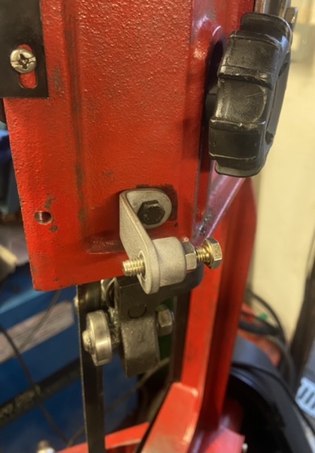
Due to the new position of the switch and a change in switch dimensions a actuator rod will be needed to cut the switch and stop the saw once cut has finished. Again this will be a silver soldered fabrication
The photos below show the progress so far:
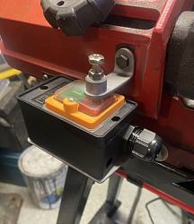
All in place ready to wire
Silver soldered fabricated switch bracket.
This photo shows the gap between the base and switch so coolant can run down between the saw and switch and not directly into a solid sheet metal bracket
Silver soldered adjustable rod stop actuator in new position. The hole to the left at 9:00 oclock is the original tapping for the old stop which was just a bent piece of sheet metal.
Method I use when ever possible to mount terminal box.
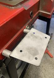
To aid the mounting of the termination box to bracket, the four holes in the box were opened out to accept M4 rivet nuts. This makes fitting and removal very quick and easy as the screw heads are external to the box and once wired can be removed without having to dismantle the switch.
The two photos show the rivet nuts in place:

For those that are interested I will update on the progress of the rewire
Thank you
The Home Engineer


 Reply With Quote

Bookmarks