Free 186 More Best Homemade Tools eBook:  
Get 2,000+ tool plans, full site access, and more.

User Tag List

Page 1 of 2 1 2 LastLast
Results 1 to 10 of 15

Thread: Precision Angle plate & V-block

  1. #1
    Supporting Member DIYSwede's Avatar
    Join Date
    May 2019
    Location
    Stockholm, Sweden...
    Posts
    634
    Thanks
    415
    Thanked 799 Times in 319 Posts

    DIYSwede's Tools

    Precision Angle plate & V-block

    NOTE: The following tools are neither from my shop nor my hands.
    Just wanting to share some odd experiences...


    Short background: Graduation time's up at the Uni where I work,
    and the other week I was given a small gift from a Master Grad, Ruben
    who've been a constantly curious, inquisitive and resourceful student/ guest in my shop:

    Precision Angle plate & V-block-johansson-25-50-micrometer.jpg

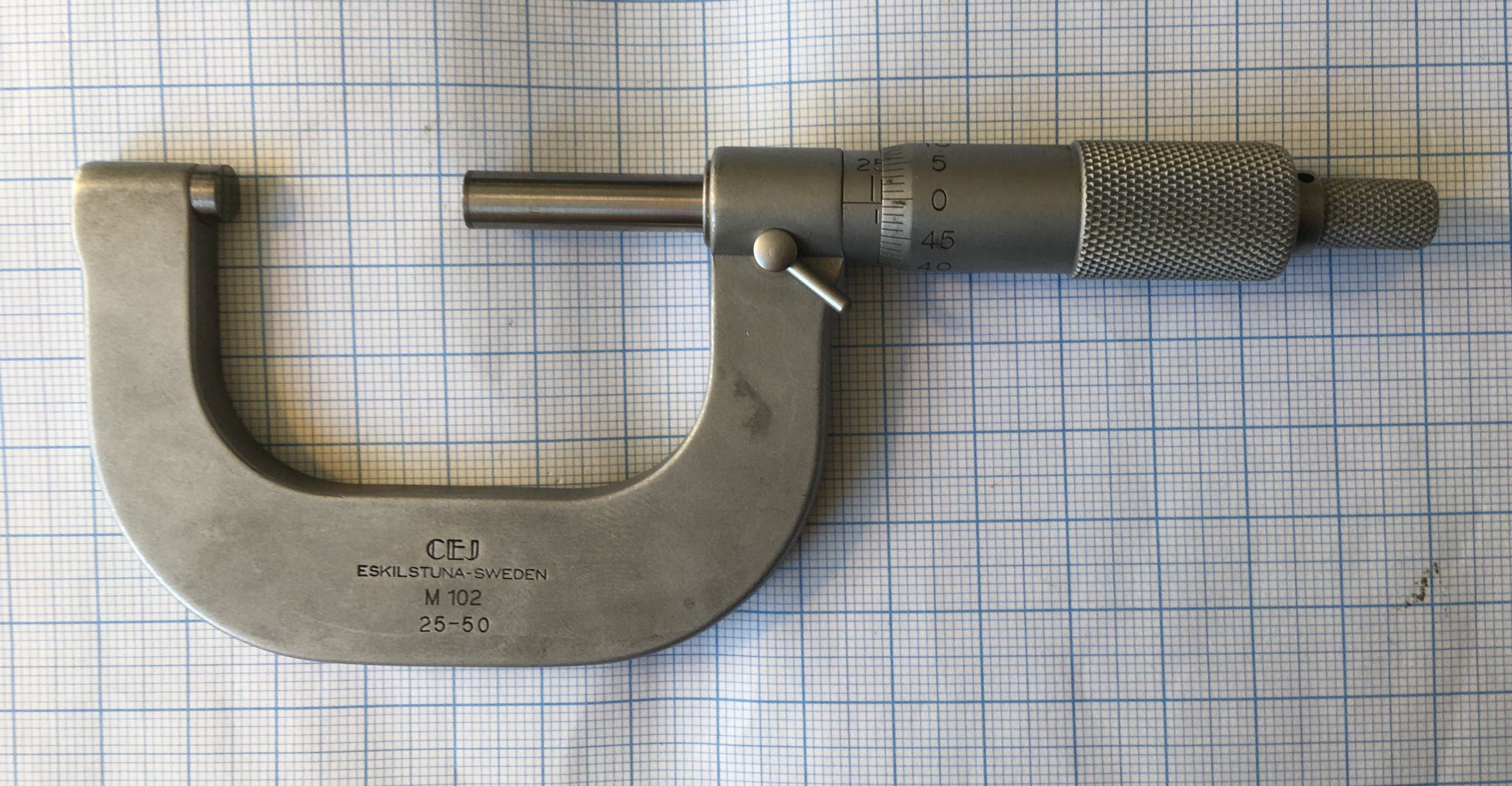
    No small gift: A C.E. Johansson (Yep - where the Jo Blocks came from) 25-50 mm grimy micrometer.
    He'd bought it in the worn-out original cardboard box at a flea market for 2 bucks...

    1 hour of cleaning, lubing ("Pjur" silicone oil for "sex toys" from the drug store*) and final adjustment:
    Right on the money - much better and more nice feel than my Chinese one of the same range.

    Today Ruben caught me in a corridor between two meetings, showing the contents of his hands with a question:
    -Johan, if you can tell me what these things are - you'll get them!

    Precision Angle plate & V-block-angle-v-blocks.jpg

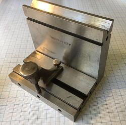
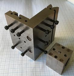
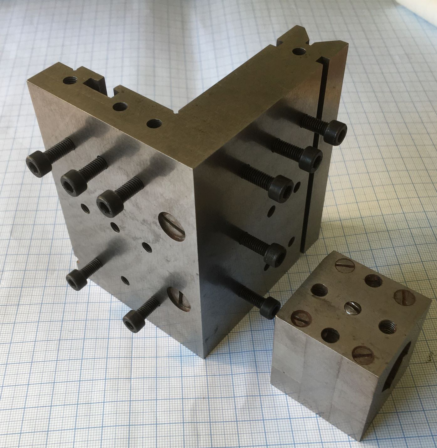
    I instantly spotted the over-engineered precision angle plate and the V-block
    (though I've never before seen any of those in my meagre life),
    and totally lacking impulse control, I blurted out the apparently correct reply.
    He seemed satisfied as he smiled, dumped them over to me and vanished down the corridor.

    Precision Angle plate & V-block-precision-angle-block-clamp.jpg Precision Angle plate & V-block-precision-angle-v-block.jpg Precision Angle plate & V-block-v-block-interior.jpg

    Info is scarce on the pieces: Bought in a flea market in small town close to Stockholm,
    previously habitated by small and big industries until the many crises thru the last 40 years.
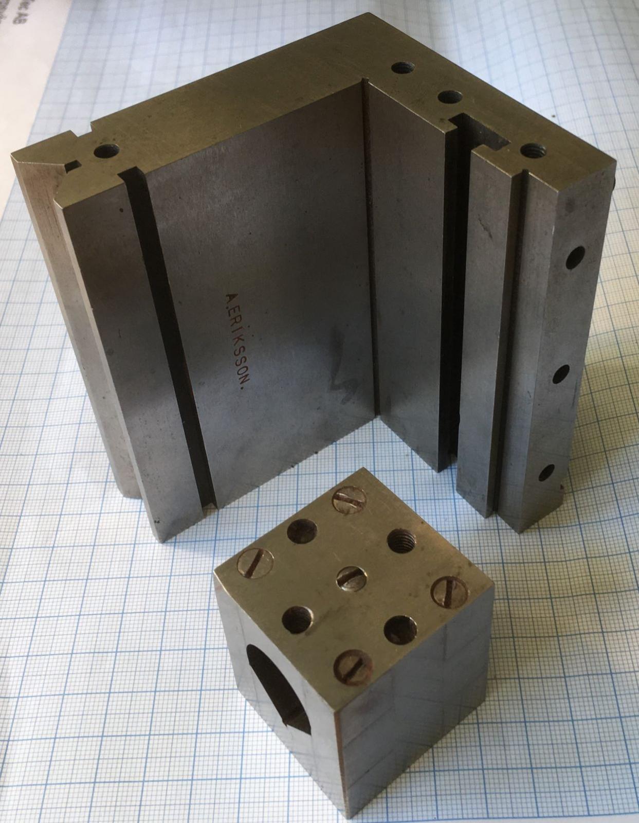
    Probably the result from an (assumed) apprentice "A. Eriksson" stamped in the vee.
    Assumption based on the odd-ball dimensions, though the work itself & grinds are flawless,
    they've also suffered some abuse from tools and handling thru the years.

    1st (crude) Measures:
    Angle plate:
    102,5 mm wide. 85,9 high x 22,5 thick. 75,05 deep x 18,0 thick.
    Its T-slot: 13,8 wide by 4,2 mm high at bottom - slot 7,3 wide by 3,3 deep
    Clamp holes: M4 with 3 rows of c-c:s 16 x 32 mm on each side

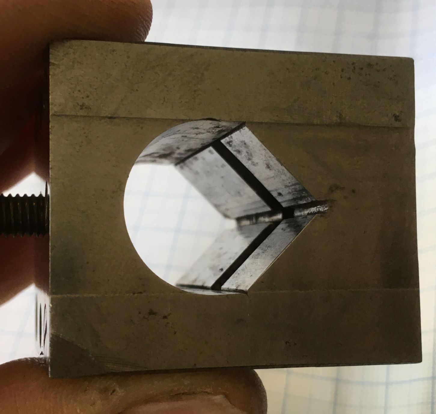
    V-block: 39 x 38,25 x 45 mm high, a two piece deal, hardly recognizable: pinned and bolted construction,
    internally transversely and centrally offset cut V-groove.

    Just wanted to share what Providence turned up (for free) to yours truly,
    while I was still desperately looking for a hardened wrist pin for a cylinder square!
    The pieces' final squareness and hardness measures will have to wait 'til my vacation starts in 2 weeks,
    when I'll completely geek down and at last return to my walk-in closet workshop!

    Cheers
    Johan "The Happy Cheapskate"

    * I even got some odd looks from the cashier, when I told her that the lube was for some "unconventional" Adult Toys.

    186 More Best Homemade Tools eBook

  2. The Following 5 Users Say Thank You to DIYSwede For This Useful Post:

    Crusty (Jun 11, 2020), old_toolmaker (Jun 10, 2020), Paul Jones (Jun 11, 2020), Philip Davies (Jun 29, 2020), Seedtick (Jun 10, 2020)

  3. #2
    Supporting Member old_toolmaker's Avatar
    Join Date
    Dec 2017
    Location
    Cape Coral, FL
    Posts
    579
    Thanks
    647
    Thanked 449 Times in 183 Posts

    old_toolmaker's Tools
    The angle plate is a most interesting tool and seems well made.
    Thanks for posting it!

    2000 Tool Plans
    Dick


    Links to some of my plans:

    https://www.homemadetools.net/forum/...965#post105972 OFF-SET TAILSTOCK CENTER PLANS
    http://www.homemadetools.net/forum/s...995#post112113 SMALL TURRET TOOL POST PLANS
    http://www.homemadetools.net/forum/l...994#post112111 LARGE TURRET TOOL POST PLANS
    http://www.homemadetools.net/forum/m...383#post110340 MINI-LATHE CARRIAGE LOCK PLANS
    http://www.homemadetools.net/forum/s...191#post106483 SMALL QC TOOL POST PLANS
    http://www.homemadetools.net/forum/q...849#post119345 QUICK CHANGE LATHE TURRET
    http://www.homemadetools.net/forum/m...949#post119893 MINI LATHE COMPOUND PIVOT MODIFICATION

  4. #3
    Supporting Member Toolmaker51's Avatar
    Join Date
    Feb 2016
    Location
    Midwest USA
    Posts
    5,331
    Thanks
    7,042
    Thanked 2,980 Times in 1,893 Posts

    Toolmaker51's Tools
    I predict you will tool-up a pair of yoke clamps for the Vee groove. People sweat under cutting the lugs for each side, so don't.
    Drill larger than max effective size Vee holds [minding that increased centerline].
    Stand up and tap for a clamp screw.
    Rotate 90°, drill and ream for a press fit dowel.
    Mill across that hole from clamp center an opening just wider than the block.
    Press short pins through either side.
    Saw off bridge at scrap end, and finish.
    If undercutting is desired, a decent Woodruff cutter will do. Hold the part up right in slotted, temporary jaws.
    Either way, a pair is worthwhile. Allows re-setting one while other stays in place.
    Sincerely,
    Toolmaker51
    ...we'll learn more by wandering than searching...

  5. The Following 2 Users Say Thank You to Toolmaker51 For This Useful Post:

    old_toolmaker (Jun 11, 2020), Philip Davies (Jun 29, 2020)

  6. #4
    Supporting Member old_toolmaker's Avatar
    Join Date
    Dec 2017
    Location
    Cape Coral, FL
    Posts
    579
    Thanks
    647
    Thanked 449 Times in 183 Posts

    old_toolmaker's Tools
    Toolmaker51,

    If I understand your suggestion correctly you are recommending using dowel pins in place of the usual 90 degree lugs. Wouldn't the clamps when loose in the slots tend to pivot on the dowels and tip to the side instead of standing up as a normal v-block clamp would?
    Dick


    Links to some of my plans:

    https://www.homemadetools.net/forum/...965#post105972 OFF-SET TAILSTOCK CENTER PLANS
    http://www.homemadetools.net/forum/s...995#post112113 SMALL TURRET TOOL POST PLANS
    http://www.homemadetools.net/forum/l...994#post112111 LARGE TURRET TOOL POST PLANS
    http://www.homemadetools.net/forum/m...383#post110340 MINI-LATHE CARRIAGE LOCK PLANS
    http://www.homemadetools.net/forum/s...191#post106483 SMALL QC TOOL POST PLANS
    http://www.homemadetools.net/forum/q...849#post119345 QUICK CHANGE LATHE TURRET
    http://www.homemadetools.net/forum/m...949#post119893 MINI LATHE COMPOUND PIVOT MODIFICATION

  7. #5
    Supporting Member Toolmaker51's Avatar
    Join Date
    Feb 2016
    Location
    Midwest USA
    Posts
    5,331
    Thanks
    7,042
    Thanked 2,980 Times in 1,893 Posts

    Toolmaker51's Tools
    Quote Originally Posted by old_toolmaker View Post
    Toolmaker51,

    If I understand your suggestion correctly you are recommending using dowel pins in place of the usual 90 degree lugs. Wouldn't the clamps when loose in the slots tend to pivot on the dowels and tip to the side instead of standing up as a normal v-block clamp would?
    They would 'lay down' to some degree, unloaded, tipping inline with Vee. At same time, being hard with minimal contact, slide easily, not shifting or bind when tightened.
    Sincerely,
    Toolmaker51
    ...we'll learn more by wandering than searching...

  8. #6
    Supporting Member DIYSwede's Avatar
    Join Date
    May 2019
    Location
    Stockholm, Sweden...
    Posts
    634
    Thanks
    415
    Thanked 799 Times in 319 Posts

    DIYSwede's Tools
    Thanks you guys for cheering and machining tips for saddle clamps-
    very unusual and clever solution with hardened dowel pins for lugs!

    I think I'll make a few after complementary checks for perpendicularity and flatness.
    The "front" clamp (3rd pic from last) seems made through benchwork only,
    very intricate profile and I assume the screws shows forms from the forties or fifties.

    The hold-down screw has a small anvil towards the milled and relieved ledge,
    anybody having a guess what (<15 mm thick) it was intended to hold 15 mm from the bottom surface?
    The top knurled screw, as well as the angle's top back shows witness marks from a few milling attempts.

    The angle's sides are not equally thick though - they both "thin out" some 5/100s of a mm from root to edge.
    I wonder what intended height the top V-groove was intended for, with what diameter for its rod?
    Interesting to see the angle's deviations/ tolerances and whether they can/ will be corrected...

    ATB
    Johan

  9. The Following User Says Thank You to DIYSwede For This Useful Post:

    Toolmaker51 (Jun 11, 2020)

  10. #7
    Supporting Member mklotz's Avatar
    Join Date
    Aug 2015
    Location
    LA, CA, USA
    Posts
    3,437
    Thanks
    357
    Thanked 6,391 Times in 2,118 Posts

    mklotz's Tools
    Another way to make low profile clamps...

    Better V-block clamps
    ---
    Regards, Marv

    Home Shop Freeware
    https://www.myvirtualnetwork.com/mklotz

  11. #8
    Supporting Member Toolmaker51's Avatar
    Join Date
    Feb 2016
    Location
    Midwest USA
    Posts
    5,331
    Thanks
    7,042
    Thanked 2,980 Times in 1,893 Posts

    Toolmaker51's Tools
    Quote Originally Posted by DIYSwede View Post
    Thanks you guys for cheering and machining tips for saddle clamps-
    very unusual and clever solution with hardened dowel pins for lugs!

    I think I'll make a few after complementary checks for perpendicularity and flatness.
    The "front" clamp (3rd pic from last) seems made through benchwork only,
    very intricate profile and I assume the screws shows forms from the forties or fifties.

    The hold-down screw has a small anvil towards the milled and relieved ledge,
    anybody having a guess what (<15 mm thick) it was intended to hold 15 mm from the bottom surface?
    The top knurled screw, as well as the angle's top back shows witness marks from a few milling attempts.

    The angle's sides are not equally thick though - they both "thin out" some 5/100s of a mm from root to edge.
    I wonder what intended height the top V-groove was intended for, with what diameter for its rod?
    Interesting to see the angle's deviations/ tolerances and whether they can/ will be corrected...

    ATB
    Johan
    IIRC, mklotz & Tony Foale presented formulae to determine maximum effective round size for a Vee. Seems to me, 70% of full distance across as a chord reveals that diameter. I have near 0 luck with searches herein.
    Far as center height, that changes with each diameter; the block may have been made for a size that matched a steady or center.
    Sincerely,
    Toolmaker51
    ...we'll learn more by wandering than searching...

  12. #9
    Supporting Member mklotz's Avatar
    Join Date
    Aug 2015
    Location
    LA, CA, USA
    Posts
    3,437
    Thanks
    357
    Thanked 6,391 Times in 2,118 Posts

    mklotz's Tools
    I certainly don't remember making such a calculation.

    If we want to determine the maximum size of cylinder the block can accommodate* we have to first establish the measuring configuration. Just spitballing, I would think something like...

    The chord between the two points of tangency of the cylinder with the V should be at least X distance below the line defining the width of the V opening. X might be defined as a percentage of the depth of the V measured perpendicular from the opening to the vertex.

    Of course, the angle of the V would need to be specified. Most are 90 degrees but 60 degree exist.

    Seems like we're not the only ones confused by this issue...

    https://www.practicalmachinist.com/v...y-mean-297809/

    --
    * A tacit assumption here being that the cylinder may not be supported on the ends of the V but rather must be enclosed within the V.
    ---
    Regards, Marv

    Home Shop Freeware
    https://www.myvirtualnetwork.com/mklotz

  13. The Following User Says Thank You to mklotz For This Useful Post:

    Toolmaker51 (Jun 12, 2020)

  14. #10
    Supporting Member DIYSwede's Avatar
    Join Date
    May 2019
    Location
    Stockholm, Sweden...
    Posts
    634
    Thanks
    415
    Thanked 799 Times in 319 Posts

    DIYSwede's Tools
    Quote Originally Posted by mklotz View Post
    The chord between the two points of tangency of the cylinder with the V should be at least X distance below the line defining the width of the V opening. X might be defined as a percentage of the depth of the V measured perpendicular from the opening to the vertex.

    Of course, the angle of the V would need to be specified. Most are 90 degrees but 60 degree exist.

    Seems like we're not the only ones confused by this issue...

    https://www.practicalmachinist.com/v...y-mean-297809/

    --
    * A tacit assumption here being that the cylinder may not be supported on the ends of the V but rather must be enclosed within the V.
    -So, for maximum dia "2r" to fit in a given V-groove (with included angle 2a),
    the dia's top must not have a greater stick-up than r+r sin a?
    Or your "X" is at least (r sin a) below the top of the V?

    Am I mistaken this late night after a full week's work?

    But before that - to even get the angle, I'll first need two dowels of different dias,
    a surface plate and an indicator with stand just to get started...

    Cheers

    Johan, "merely Pure Obsessive"
    Last edited by DIYSwede; Jun 12, 2020 at 03:58 PM.

  15. The Following User Says Thank You to DIYSwede For This Useful Post:

    Toolmaker51 (Jun 12, 2020)

Thread Information

Users Browsing this Thread

There are currently 1 users browsing this thread. (0 members and 1 guests)

Bookmarks

Posting Permissions

  • You may not post new threads
  • You may not post replies
  • You may not post attachments
  • You may not edit your posts
  •