I would look at a buck and boost transformer The machine tool may need the adjustment too. They are 50Hz too
Dave
Quote:
Originally Posted by nhengineer
I would look at a buck and boost transformer The machine tool may need the adjustment too. They are 50Hz too
Dave
Quote:
Originally Posted by nhengineer
If the idler motor is 50Hz then its output will also be 50Hz. By the way, a 3-phase 50Hz motor is quite happy to run on 60Hz 3-phase. It will turn about 1.2 * faster than that which is written on its nameplate however.Quote:
Originally Posted by smithdoor
I'm wondering, Dave, what will be accomplished with a buck/boost transformer? The issue here is most former United Kingdom locations are 220 (230 now actually) with a single hot lead and a neutral. In order for my present design to work, there needs to be two hot leads (out of phase with each other) with reference to earth ground.
Yes they change the voltage starting 1980's was switching from 240 to 230 volts it was a 20 year plan with a low limit of 216 to high limit of 253 volts. This at the meter
If you have long run from the meter to tool you then have a greater drop
So if need to adjust for a motor it simple with a buck and boost
As far as 50 Hz to 60 Hz
The tools I had it past that had 50Hz motor I just ran tools for 20 year or more on 60Hz be for selling the tools working great on 60Hz. Some castes I replace the pulley with smaller one so RPM plate was right.
Dave
Hi. Three phase motors are very cheap. The junk yards sell them for scrap price here. I have a 7 1/2 HP they sold me for 14$. And most single phase motors 1/2 hp or bigger will spin a big 3-ph one. I have all the components to build one right now but, if I use my 3-ph motor for a converter I won't have anything 3-ph to run. Go figger.
Sound like it will work
Do you photos or drawing you post
If you using a three-phase motor as you converter it is working as a generator making as some call the third leg
Dave
Quote:
Originally Posted by Marc Broussard
My rotary phase converter is kind of small actually too small in some ways,being only a 3 Hp it is started by the use of 3 large capacitors with no small spin up motor. I really need to build a larger one with a spin up motor but it came with my lathe when I bought it and has been running it for a few years even though my lathe is 4 hp, as long as I don't try to make a .200" cut @ .015" feed it does just fine any heavier cut and it will bog down.Also I have found that if I switch on my 3 Hp mill and just allow the motor to run without any work being done then the lathe do a little better when starting it or reversing it.
I an thinking that when I build a larger converter I will use a 1/2 or 3/4 Hp spin up motor direct coupled to a 7.5 or 10 Hp motor with a large flywheel to help with the higher current load my 450 Amp mig welder will require
They not hard to build
I have simple drawing just using a AC potential relay and starting capacitor
Here is the drawing
Dave
Quote:
Originally Posted by Frank S
I do not have a copy of nhengineer's plans, but using them with 220V, single phase power should be possible. The 220V supply with one end grounded can be easily passed through a 1:1 transformer with a center tapped secondary. Then that center tap on the secondary would be connected to ground and you instantly have the exact same "two phase" dual 110V supply lines as are used in the US. The transformer would need to be sized properly for the load current, but it should work just fine. I would expect for it to cost a bit, probably more than the junk yard three phase motors, as it would be a more useful item.
As an alternative, you could use two step down transformers that each produce 110V on their secondaries and connect those secondaries in series with that common connection grounded. That is exactly the same thing electrically and those may be easier to find. If you are in doubt about the series connection of the secondaries, you only need to measure the Voltages. If they each produce 110V and you measure 220V across the two in series, then the connection is correct. But do this before connecting any load circuitry.
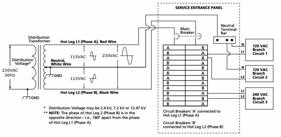
Note: I know my use of the term "two phase" above is unconventional. But, IMHO, it does accurately describe the household power here in the US. There are two separate Voltages and they are 180 degrees apart so they ARE two distinct phases. The problems discussed in this thread strongly support that use of the terminology. But I do understand why, here in the US, it is referred to as single phase. That is because it is derived from a single phase of the three phase lines that are used for the transmission of that power from the generating plants to our neighborhoods. It is only in a transformer that sits on a pole that is within a few thousand feet of a home or other user that it is converted from a single phase, 5KV or 10KV line to the 120V-G-120V configuration that we all use. I do like to think of those pole transformers as single phase to two phase converters. And BTW, those pole transformers are just larger versions of the center tapped transformer that I am suggesting that you can add in other countries where single phase power is really just that, SINGLE PHASE. Electrically there is absolutely no difference.
So please don't jump on me for using the term "two phase" for US power. PLEASE! I have been through it before.
Hi Paul,
I had been thinking about a 230-0-230 volt transformer arrangement such as is used in electronic circuit supplies (usually 25-0-25 for medium output amplifiers), however, as you point out, the phases are in fact 180 degrees out of phase not 120 and I did wonder how that would effect the performance of the motor, in that it would "confuse" the third phase orientation.
Regards,
Rob.
No this does not work this only 180 deg you need either 90 (2 phase) or 120 deg (3 phase)
Even single phase motors cap start has 2 phase winding for starting
I think most of wish that wood work too.
Dave
Quote:
Originally Posted by Paul Alciatore
Not to be splitting hairs here but the term for the US 2 120V lines coming into a house is called split phase and yes it is actually created from center tapping the transformer on the pole to create the neutral. I one looks up on the crossbar of the pole and sees only 2 wires for the transmission lines 1 is the ground and the other is the 13.2 KV high voltage the 3 out put lugs will be 120-0-120 or communally known as L1 N L2 when this enters the service panel the N or common is connected to the terminal strip on the side of the panel this is where all of the white wires are connected the bare ground wires are also connected to this terminal strip or may be connected to a desperate terminal strip but even so both terminal strips are connected together to the incoming neutral Plus the wire coming from the grounding rod driven in the ground near the main panel creating what is called a bonded ground
Now all 220v appliances receive their power from the L1 and the L2 and would be perfectly happy to have only 2 wires connected to them except for 2 things first would be the lack of safety without the ground . 2nd all controlling circuits are derived from either the L1+ the neutral/ground or the L2 + the neutral/ground in some rare instances where there happens to be more than 1 set of controlling circuits or the load of the controlling circuits and other 120v loads are enough to create an imbalance the loads may be split between both lines.
European 230v single phase equipment have only 1 power leg and 1 neutral leg+ ground
Now a 220v rotary phase converter in the US can actually be nothing more than a simple 3Ph motor with the 2 120v lines connected to the T1 and T1 terminals of the motor but this will not allow it to start up because as mentioned in previous posts the legs are actually 180° apart. Therefore some means to starting it to rotate is required this is accomplished by using either a pony motor to spin it up or a bank of capacitors connected to to the L1 or L2 at the T1 or T2 terminal and the neutral line to charge the capacitors the output terminal of the capacitors is connected to the T3 terminal. It is best to have a switch or a timed relay to charge the capacitors before switching on the converter motor but in the case of my 2 HP converter there is none this means the converter can take up to 15 seconds before reaching run Speed. on larger converters this would mean the inrush current would remain high for several seconds and possibly even a full minute which could cause a breaker to trip.
There was a discussion about single phase capacitor start single phase 220v motors in these there is a separate winding that is wound 1 tooth out of sync with the other winding's there is also a centrifugal switch that cuts the start winding from circuit after the motor reaches full speed. There are also motors with both start and run capacitors this is to assist in balancing the loads of the field winding's' when the motor is under load this arrangement is usually found in single phase motors that are started and ran constantly under heavy loads.
Some larger 3 phase motors are wired both in star and delta with 2 magnetic motor controllers these will be started with star then once up to speed will switch to delta or vice versa I forget which.
Then there is the DC start motors which are usually in the size range of or 1200 HP or more where the motor uses very high amperage 96 VDC to make it start rotating then as the RPMs increase it is switched to 4100 or 4300 Volts AC
1 last note if there are 3 wires on the pole it means that there are 2 13.2 KV lines and 1 ground all is needed there would be a 2nd transformer to get 3 ph by using the center tap method of the first and tying 1 leg to 1 of the input legs of the other then another connection is made from the grounds and one other lug I forget which it is but the output will be 120 198 120 which will give about 208 across any 2 legs
for true 220/240v 3 phase or 460V this requires there to be 4 wires on the pole and 3 transformers for the incoming line voltage
I hope I have not completely confused the issue
Hi Dave,
These are precisely the considerations that have stopped me proceeding with experiments in that area to date.
I have seen commercial converters and I think that they use a lead and lag circuit based on inductors for one side and capacitors for the other leaving a primary circuit in the middle as the center phase, but they're very expensive.
Regards,
Rob.
All the parts for a static cost from Amazon is around $35.00 for 5HP FYI you need a potential relay I like APR5 works the best
Now if find a old use 3 phase motor star wound now you have rotary converter
You can add oil run cap make look better but that all
Dave
Quote:
Originally Posted by old kodger
Hi Dave,
I quite readily concede to not being an expert in anything, so, when I say that all of the info on potential relays that I have managed to locate on the net, seem to refer to "split phase" power supplies I can comprehend how the relay works. However, I'm in Australia and our 230 volt supply is ONE HOT LINE AND ONE EARTH BOUND NEUTRAL. there is ,L1 or L1 or L1, there is NO L2, so unless I'm missing something fundamental here (if so, I hope you will explain), I cannot see how a potential relay is going to help.
Regards,
Rob.
Rob,
I feel your doubt. In fact, in spite of a background in physics and math, it took me some time to come to the realization that it is possible to get real three phase from a pair of Voltages that are 180 degrees out of phase with each other. It seems to be contradictory, I mean just how do two Voltages that are 180 degrees out of phase suddenly become 120 degrees out of phase? In most phase converters those original two phases are just passed through with no change. But when you do the vector math, it really does work. In fact, this is exactly what is happening when, here in the US, we take a 220V feed (call it single phase or two phase as you like, that's just terminology) and, using a rotary phase converter to convert it to three phase.
The "magic" lies in the vector math which shows a change in the ground reference. When a rotary phase converter is used to generate a third leg from the two existing phases of the power feed, although it does not actually generate an actual, new ground point, the third phase is generated in a manner so that the theoretical ground point is shifted in both Voltage and phase from the original ground point that is half way between the original two phases. And those original two phases are not changed in any way, but from the viewpoint of this new, theoretical ground point they REALLY are 120 degrees out of phase. This is at the same time that those original two legs are still 180 degrees out of phase when viewed from or referenced to the original, earth ground point. It sounds contradictory and I had to work out all the math before I was ready to believe it, but it does really work.
So, if you first convert the real single phase current which has one side grounded and the other at 220V to the 110V-G-110V configuration used in the US and then run it through a rotary phase converter, then you do get actual, true three phase. In fact, if you are using a rotary phase converter, you do not even have to use the transformers to convert it to 110V-G-110V, you can just use the 220V power from the wall outlet directly to the rotary phase converter and it will still work and produce true three phase.
This will also work for any other kind of phase converter that produces three phase from single/two phase. I talked about using the transformers because I do not have a copy of the plans being sold and I do not know if they require the center ground of the 110V-G-110V system or not. There are many schemes for producing three phase from 110V-G-110V and some of them may very well need that center ground.
Quote:
Originally Posted by old kodger
Dave,
I am not sure that I understand your objection. First, there is an old, antiquated two phase system which had a second phase that was shifted by 90 degrees from the first phase, but that is no longer used anywhere that I know of and is completely irrelevant to this discussion. If you understand the vector math involved, you will see that two phases that are 180 degrees from each other can be viewed as being 120 degrees apart if the ground reference is shifted. This is what most, if not all, phase converters do. Please read my previous post, above.
It WILL work.
Quote:
Originally Posted by smithdoor
The relay turns the start cap off after the motor starts
The potential relay APR5 is adjustable for voltages (130-370Volts)
You find this type of relay use in AC and deep well water pumps
I replace centrifugal switch found in single phase motors
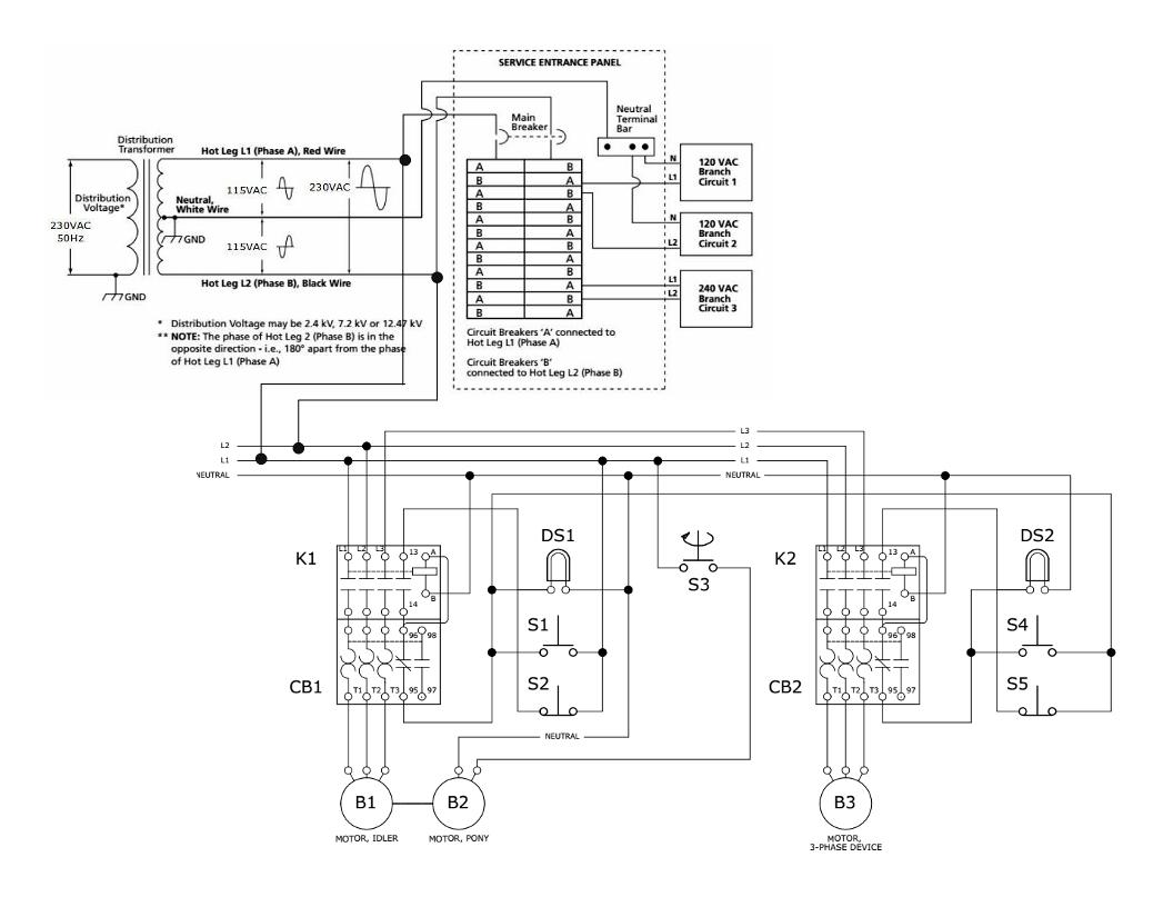
The first drawing below shows a typical single phase motor use a potential relay
Note the start winding is 90° to then main winding this give the motor the direction to turn
For three phase the winding are at 120° The second drawing shown how it is wired for three phase
Dave
Quote:
Originally Posted by old kodger
To run a RPC (rotary phase converter in Australia, if you are in rule areas you could have what some call 2 ph 480 which would be to hots and neutral. but most areas without 3 ph or the rule areas with 2 ph there is only 1 240v line with a nuetral. to make a RPC run in those places a transformer would be required to make the 415v split phase L1 +N for input then tap at 175-0 240 +415 nominal for output. then connect the 2 output line to the PRC and the cap bank for starting and a module of thyristers for full balanced true sine wave 3p output.
Here is a commercial site selling their product but the information there will give you an idea of how to go about it
3 Three Phase Power Converter Australia converts single phase to three phase.
I think if it were me needing to do this I would buy MR nhengineer's plans then go from there adding what might be needed and contacting him for assistance
Look the Single to three phase converter in Australia converting single phase power into 3 phase power web site
It use a potential relay with a starting cap and run cap as shown in my drawing
They did add a step up transform to 415 volts
Odds are you can buy all parts from a AC supply or pump supply company for around usa $35.00 and add a transform if need.
Dave
Quote:
Originally Posted by Frank S
Yeah, I'm wondering how, with a 230V single phase; that is, one hot leg and earth ground the other, as in Australia, you could create an additional phase, whether it be 90° or 120° out of phase with the original simply by using a transformer.
...and by the way, the pony motor need not very large regardless of the final load. It only needs to be large enough to overcome the 'at rest' inertia of the idler motor's armature and the friction of its bearings. Its only purpose is to get the idler motor turning under no load.
Hi David,
Yeh, I'm with you on that one, the only way I could see of getting plus 230-0-minus 230 would be to get a big old 450volt output tranny with a center tap and use the center tap as the ground reference.
With two trannys working in tandem you'd still only get two lots of 230 IN phase.
I got this far and suddenly realized that if the two were tied in the middle and that junction grounded, you may very well get plus 230 and minus 230 at the other ends of the transformers, though whether they would be out of phase is still questionable.
Any thoughts on this?
Rob.
I think there may be a very valuable point being missed here. All households in the USA have only 1 ph it is called split phase for a reason the 13.2 KV line on the pole needs onlu 1 hot and 1 earth to make the primary winding in the transformer function the secondary is tapped in the center or the (0) then tapped at the 120v stage on both ends this makes the 2 hot lines coming in the meter then to the main panel The only exception to this is the higher end larger homes that require 3 ph to run the HVAC equipment or on farms such as dairy which have lots of 3 ph equipment
Therefore Rorary phase converters used here in the US are receiving 2 hot lines at 180° once the Idler motor is running the output will be 3ph although without the use of tryristers it will not be true 120° ph to ph pure sine Most motors and some transformer induction equipment don't care it is only when the introduction of 3 ph CNC equipment to the system does the true sine 120°ph to ph matter.
In Australia the 1 hot could be considered to be just like the incoming pole line albeit at a much lower voltage.
so for a 10 HP idler motor one would need a simple multi tap transformer about 9KVA in size 1 hot 1 cold to the primary then tap the center for the neutral output and which ever voltage desired for the split phase output Normally in Au it would be around 415 across the to hot out lines but if you have 200/208, 220/240 3 ph equipment you are needing to run tap the transformer so you would have 120 -n-120 then to the idler. for the 3 ph output
Remember for 415v Single ph across the 2 lines you would want 230-n-175
Split phase is type of motor
Lower in cost over capacitor start motor
In the USA 120 volte to ground is used for safety
Dave
Quote:
Originally Posted by Frank S
Split phase is also the type of current here in the USA When talking about 220 v single phase
some mistakenly say there are 2 phases of 120v to get the 220 volt when actually it is only 1 phase split in the transformer to achieve 220v
Split phase is also used in rule Australia to get 480v
You can find on the internet split phase
If you split the phase it is now 2 or 3 phase this is used for starting motor
Even Wikipedia is not clear
If even send a center tap transform some will call this split phase. But it is still single phase
They have even made 6 phase for electronic work, this most I have seen
Dave
https://www.merriam-webster.com/dictionary/split-phase
http://3.bp.blogspot.com/-CuAIHuX75Q.../s1600/6.8.png
https://en.wikipedia.org/wiki/Split-...electric_power
Quote:
Originally Posted by Frank S
FYI
The most command types of motors use for Synchronous single phase today
1) Shaded pole
2) capacitor rum
3) split phase
4) capacitor start
5) capacitor start and rum
They made other types in past did list most where not made after the mid 50's
Three phase is just three phase motor they do not need a starting winding
Two phase I have not seen but is some time found in electrical books
A transform was made back the early 1900's from converting two phase to three phase or three to two phase. I do not know if this was true sync of wave or not
Dave
Gotta think on that one a bit.
Here we are taking about using a capacitor to delay the power for abut .006 seconds making a two or three phase wave. Given the motor the direction to turn. (this can be done with either a pony motor (using staring cap) or using staring cap in the main motor)
After the motor is turning at speed the start capacitor is turn off as this will shift the phase great than need.
At this point the main motor is turn into a generator. Generating the three phase power or if using static type converter the motor is running at 60% power.
Dave
Well Frank S, after further review, I believe you may be correct. See drawing below:Quote:
Originally Posted by Frank S
Attachment 16140
Image modified & copied from HERE
It appears that my design, slightly modified, will work for Australia and other former British Crown Colonies nations. All one would need is an appropriately sized transformer. I will work on that.
Reader comments welcome.
That is still single phase in drawing with center tap transform
I see why the confusion But this is single phase power AKA as 3 wire single phase
This type is use all over the USA & CA for homes and offices 3 wire. A long time ago they found this voltage use homes was safer than 220 volts.
Most do know this today is at time the USA had both 50 & 60 Hz about 40 years a hear of this from old time electrician having to convert to 60Hz . The only time may see this is on very old motor lay around in old shop
Dave
Quote:
Originally Posted by nhengineer
Bravo! That's what I was saying. Thanks for the drawing.
Quote:
Originally Posted by nhengineer
Please Smithdoor, go look at the drawing again and then follow the link. It is clearly explained, both on the drawing and in the text of the link, that you begin with 2-wire single phase (left side of drawing) and wind up with 3-wire 2 phase 180° apart (middle of drawing).Quote:
Originally Posted by smithdoor
Yes it say split phase so NOW it on the internet it must be true
But when make drawing for the city or county That is a 3 wire single phase
That will not start a 3 phase motor with additional caps for starting and last I heard We are taking about 3 phase
Good luck with internet
Dave
Quote:
Originally Posted by nhengineer
Geekers Smithdoor, we're using a pony motor to start the idler turning. I'll post the original schematic to show the original design but I'll have to reboot first.Quote:
Originally Posted by smithdoor
I just look at your drawing on the first page
I like using a simple way capacitor and potential relay
Low cost an time proven Today it use for AC and water well pumps on single phase
I have seen the pony type with no more than a lawn mover pulley and rope for starting it works and simple
The one I saw the guy raped the rope around the pulley mounted on the idler motor, pulled the rope and switch the motor on it work. I could not use with employs. so I used capacitor and potential relay it is automatic
Dave
Quote:
Originally Posted by nhengineer
The trick is to find the appropriate transformer that is 1:2 with a center tap on the output. That will take some research on my part. (corrected 2017-01-18)Quote:
Originally Posted by smithdoor
Attachment 16149
Smithdoor, we are going from 2-wire single (one hot & one earth ground) to 3-wire 2-phase (2 hots & one earth ground) to 4-wire 3-phase (3 hots [kind of] & one earth ground). The required transformer (if it exists) would not be cheap but probably more economical than purchasing a single phase motor to drive the equipment.
There is a 3 wire 2 phase this drawing is not 2 phase This is 3 wire single phase
Yes it said on drawing some else but it is only wishful thinking only
At one time there was 4 wire 2 phase power in the USA back about 1900 come from power plants it died
It is on internet it must be true but still will not work.
Dave
Quote:
Originally Posted by nhengineer
Hi Rhengineer,
The transformer thing will likely work, but would it not have to be 1:2 in order to input 230volts and get two lots of 230 volts (center tapped) 180 degrees out of phase?
Also, each time an idea (opinion) has been postulated on this thread, I've gone and done whatever research I could, and in every case IN AUSTRALIA the cost has not been justifiable.
Now to throw another consideration into the fray, since the acquisition of an idler motor is mandatory in all instances, if one were to forcibly drive an idler motor with say, a diesel motor, (motors from old banged up utes are not so hard to get), would it produce all three phases?
Rob.
What you would be doing there is building a generator then you would need an AVR ( automatic voltage regulator) to hold it at the correct HZQuote:
Originally Posted by old kodger
Also without line voltage to the motor now being used as a generator it would require a source excite the field winding.