You did not post any thing
PC error
Dave
Quote:
Originally Posted by nhengineer
You did not post any thing
PC error
Dave
Quote:
Originally Posted by nhengineer
Quote:
Originally Posted by smithdoor
This is becoming a real challenge Mr. Smithdoor. :headshake:
Are you out there Rob? :smash:
What planet am I on now? :lol:
DSLee,
Yeh, I'm out here (there)
I'm not sure, but I think it must be a different one to most other people. Maybe that's why I didn't post anything.
Regards,
Rob.
After some interesting reading I just have to get in on this discussion. I fail to see the difference between a 208-230 volt three phase US motor and a 3 phase motor used in Australia except the nominal RMS operating voltage and the frequency. A 208-230 volt single phase motor used in the US expects to see between 208 volts and 230 volts between it's two input terminals to operate around motor nameplate HP, current, and RPM (these are a function of motor load). Does this single phase motor know it has two separate phases as referenced to the neutral (AKA the midpoint of the transformer). Let's let one of the input phases (say L1) be the 0 volt reference point for L2. So now L2 referenced to L1 is a 208 to 230 volt sine wave at 60 Hz in the US. In my opinion that is why this is a single phase motor and not a two phase motor. Is the single phase motor in Australia any different? If we can rotate an unloaded 3 phase motor with single phase power in the US why can't they rotate an unloaded one in Australia with single phase power? Is anyone following my reasoning here?
Just wondering
Junker2
AKA Terry
The 208 is used for offices for 120 volt with 3 leg save on cost of wire
The 240 is for shop use
This why some shop have to use 208
Dave
A three phase motor will NOT rotate on single phase. At least no three phase motor I've ever used would. None would even rotate on two phases without a pony motor to start it up. Where are you getting that from Terry?Quote:
Originally Posted by Junker2
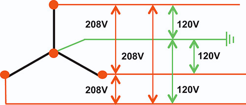
By the way, 208 is a product of a 3-phase "Y" generator.
Attachment 16773
If you have 208V, it is unlikely that you have 240V too and the converse it also true. It has nothing to do with the location being home, office or shop. It is what your local electric company is producing.
Junker,
In my opinion we are saddled with some unfortunate choices of terminology in the field of electricity. And there are those who will fiercely defend those definitions of terms, no matter what the evidence to the contrary may be. I am a citizen of the US and have never visited Australia, but it is my understanding that 220 or 230 Volts at 50 Hertz is the standard there while here in the US we have a 115/230 Volt standard that is commonly referred to as "split phase". But from some reading it would appear that in some installations the Australian 230 Volts can also be split to two 115 Volt "phases" by the addition of a neutral wire, just as is done in the US. Also, in the US the neutral wire is often not used for a 230 Volt outlet, making it more like the Australian. Things like an air conditioner or dryer outlet will not have a neutral connection in the socket. None of the 230 Volt outlets in my home and shop have a neutral connection: they are strictly 230 Volts, period. So, it would seem that the difference between the US and the Australian systems is more one of emphasis than strictly that of form. Both systems allow and encourage the use of a safety ground connection for many, if not all, service outlets. But this safety ground is just that, a safety ground and it is not to be used for powering any circuit. That would be the job of the neutral conductor if it is present.
At the risk of being drown with abuse I would like to say a little more about the terminology. In the US we have a feed from the power poles that commonly is 115V - 0V - 115V which gives us the 230 Volt connection between the two 115V wires. These two 115V feeds are essentially 180 degrees out of phase with each other so, by vector addition, they add up to 230 Volts. Notice that I brought the word "phase" into the previous sentence. They "are out of phase" with each other. Now, from the viewpoint of vector math, that is the very definition of being different. They are DIFFERENT PHASES. But they are derived from a single phase of the three phases that are used to distribute power over the long lines around the country and around the city or local area. A single transformer with it's primary winding connected to a single one of the original three phases from the generator station is used to drop that higher Voltage down the the 230 Volt level. But the secondary winding of that single transformer has a center tap that is grounded with a ground wire that runs down the local power pole to a ground rod in my neighborhood. In my view it is this grounded, center tap that converts that single phase power on one side of the transformer to a split phase or TWO phase power feed on the secondary side of that same transformer. It is physics, not magic. AND, there is absolutely no reason why the same exact thing can not be done with Australia's 230 Volt, single phase power. And it can be done inside your house or shop just as it can be done on a power pole. Now, I know nothing about Australia's electrical code or regulations so whatever is done must be in accordance to those limitations.
But notice that in doing this, NEITHER of the split phases, of the two 115V phases is grounded. The ground is at a point that is exactly half way between them and this is the important point here. You should never attempt to connect either of the Lines of the 230 Volt feed, either in the US or in Australia, to ground or to neutral, which is also connected to ground. This would instantly blow a fuse or breaker.
A single phase motor will not "know" any of the details of the lines that are feeding it. A 230 Volt motor could operate quite happily with two lines at 100 Volts and 330 Volts respectively. It will only "see" the difference between them or 230 Volts. And it certainly does not know or care about what terminology that we arbitrarily apply to these power feed wires. The only concern here would be for the Voltage rating of the insulation inside the motor that prevents the line Voltages from being shorted to the frame of the motor which would probably be grounded one way or another.
An unloaded three phase motor, AKA a phase converter, CAN be powered from a single phase in both the US and in Australia. There will be some capacitors involved that will generate a third phase for the third input wire on the motor. In a capacitor the current will be out of phase with the Voltage and this capacitor(s) will be sized so that the third phase that is generated is 120 degrees out of phase with the original two phases of the power line. Notice that here I am forced to refer to the two power lines as a two phase feed. Otherwise, there would only be two phases on the three terminals of the three phase motor. And here is the real magic: if the capacitor(s) are properly sized for the rotary phase converter system, then the terminals of that idler motor and of the motor being powered by it will actually see three phases that ARE 120 degrees out of phase with respect to each other. This magic has been accomplished with vector math that effectively creates a virtual "ground" point that is at yet another phase angle and it's own Voltage value with respect to earth ground and the original, single phase power on the pole before the pole transformer. Not really magic, but vector math is involved and, as far as I can see, is the only way to properly explain and predict it.
The only complicating factor that I can see here is with the difference between the actual, earth ground/neutral point that physically exists in both countries systems and the different, virtual neutral point that is created in any conversion from single phase (split phase or what I call two phase) to the three phase needed by three phase motors. Some methods of creating the third phase do not have any connections to the earth ground/neutral and these methods should work just fine in both countries' systems. But other methods will have connections to that earth ground/neutral point and then care must be taken to insure that the point actually used is indeed the half way point between the two sides of the 230 Volt power feed. This distinction should be possible from a careful examination of the actual circuits involved. But in some cases, like a VFD device, that may not be easily possible and you will need to consult the manufacturer.
Quote:
Originally Posted by Junker2
junker2,
"is the single phase motor in Australia any different?"
The motor, no; but the power supply IS.
Since this thread is about single to three phase conversion, single phase motors are really not under discussion. So, one more time, I don't know your location, but I would guess that you're in the USA. I the states you have the capability to split 220 volts into two single phases of 110 volts thereby enabling you to maintain the speed of a 3 phase motor with 2 phases, IN AUSTRALIA WE CANNOT DO THAT single phase is one hot line (L1) and ground (no L2).
Rob.
paul,
It was not until I had answered junker2 that I read your post. Whilst I have not read all of your post, the misconception is contained within the first paragraph.
"it would appear that in some installations the Australian 230 Volts can also be split to two 115 Volt "phases" by the addition of a neutral wire"
Not so under ANY circumstances. Single phase here is ONE hot line and ONE neutral bonded to ground, and cannot be split except with a 1:2 center tapped transformer where you will get the high end of the transformer putting out 220volts, and the low end of the transformer putting out 220 volts 180 degrees apart.
Incidentally, 3 phase here is three separate phases of 220 volts 120 degrees apart.
Rob
Paul, the first incorrect assumption you made is that electric service in the USA is 115/230V. Wrong. If you want 115V (I cannot imagine why you would) you would need a buck transformer. 125/250V is pretty much standard from generating stations in most metropolitan USA locations. By the time it gets to your house or shop, losses could have taken away as much as 10% giving you 112.5/225V but that is highly unlikely unless you live way way out in the boon-docks.Quote:
Originally Posted by Paul Alciatore
Intending no disrespect but the rest of your manifesto is equally inaccurate. I only mention this, not to embarrass you, because there are some folks out there the may believe it and that could be dangerous for them.
Thank you.
Oh for gosh sake! The electric Voltage in the US has been specified, stated, and generally assumed to be anything from 110/220 to 130/260 Volts or even more. It is not and never has been any exact figure and I have seen various specifications put forth by different power companies in different regions/states. Many people simply say 110/220 Volts. Nameplates on appliances generally show a number between 110 and 120 VAC but they can show other values. 230 Volts is a commonly used number for motors: I can not remember seeing even a single nameplate that used the 250 Volt number but I would not be surprised if there were some. For a time 117 VAC was a commonly used number, probably a compromise due to the confusion. And 117 is approximately half way between 110 and 125 and that range is generally assumed to be where most power lines and most appliances will exist. Most, dare I say all appliances and devices sold in the US WILL work just fine on any Voltage in the range from 100 to 130 Volts or perhaps more.
I have measured the line Voltage on many occasions and always get a different figure. And it can vary during the duration of a single day. Just for fun I cranked up my best digital meter and measured the line here at my desk. It was 126.4 V. So what? It will be different tomorrow morning or at midnight or next week. It is probably different for different houses on my block that are on the same pole transformer as the copper losses will be different to each one. I would likely get a different reading if I took that same meter to my bedroom or garage/shop. Oh, and in one location where I had line Voltage monitoring equipment I have seen the line Voltage go as low as 85 Volts or so. An aluminum processing plant had their furnaces on the same feeder and when an additional one came on line, the Voltage really dropped until the local utility was able to bring more capacity on line. Sometimes that took as much as a half or even three quarters of an hour. And that was in a major metropolitan area, not out in the countryside. This was an unusual situation, but it did happen and not just once, but often two or more times in a week. What I could not understand was why the local power station, which was in the same general area, did not take more effective measures. I also do not understand why it took so long to slowly come back up to normal.
I choose to use the numbers 115/230 V as a way of more easily saying "whatever the local line Voltage presently happens to be, somewhere between 110/220 V and 125/250 V" which is rather lengthy. But if you really want to be completely precise, then please feel free to go over my post and substitute that language for every place where I simply said 115/230 V. Personally, I think my post was long enough already.
You say the rest of my post is also incorrect. In what way? You do not say. I have had some struggles with understanding the fine points of deriving three phases from what is called single phase and I have read a lot about it as well as giving it a lot of thought. I would appreciate a clarification. And don't worry, I won't be embarrassed.
Quote:
Originally Posted by nhengineer
Are you in Australia? And have you actually measured the potential (Voltage) on the two pins of a 220 Volt outlet with respect to earth ground? I am not trying to be funny, I would be highly interested in that measurement as I could not find any definite information on the actual relationship between the two lines and earth/ground in the Australian power system. Although I did see some references that seemed to be saying that it was much like the US system but they just never or at lease very rarely actually ran a neutral conductor to any outlets.
Apparently some outlets in Australia do have a safety ground connection. I would greatly appreciate it if one or more Australians would take three measurements on such an outlet: L1-L2, L1-G, and L2-G. and post the actual numbers.
In any case, if an isolation transformer with a one to one turns ratio were used then even a 220 V feed with one side grounded could be rearranged to have the 110V-0V-110V configuration of the US system. This could be done in Australia or any other location in the known universe where a 220V, grounded power exists. So it CAN be done in Australia, it just may cost more.
Quote:
Originally Posted by old kodger
paul,
Please get off of the grass, I tire of this, I LIVE in Australia, please don't presume to tell your granny how to suck eggs! I've just measured the line voltage and it is 236.5 volts most often referred to as 240volts (not 220), I used the 220 reference so as not to further confuse the issue for Americans
Across the two "hot" lines I can measure nominal 240 volts, between one hot pin (in the socket) and the ground (safety) pin I can measure 240 volts, BETWEEN THE OTHER "HOT' PIN AND THE GROUND, THERE IS NO POTENTIAL DIFFERENCE, i.e neutral is bonded to ground.....NO L2!
With respect to transformers, Nhengineer and I have discussed this, the cost here for a transformer to produce two phases 180 degrees apart, and incidentally they have to be 240 volt phases because there are NO 120 volt motors of any sort, in this country, (the nearest we get to 120 volts is in walking machines which are 180volt DC single phase motors) is in the order of thousands of dollars. It would be far and away cheaper to buy a 3 phase generator, and most likely more reliable in the long run.
Rob.
Rob.
Rob,Quote:
Originally Posted by old kodger
I could not have created a better response myself. Thank you for saving me the time and effort.
Paul,
As with Rob, I tried of this exercise also. In addition, the time I spent learning power distribution at Franklin Institute of Boston (Massachusetts, USA) cost my parents a fortune. You could enroll there yourself ( Home - Benjamin Franklin Institute Of Technology ) or you could listen to Rob; your choice. Regardless, I do not have the time or inclination to provide free education. I have other projects to work on. Anything you would need to know regarding this subject you should be able to find using proper Google search phrases.
Best regards,
David Lee
I think you will most of the world is slowly switching to 115 volts over the old 220 volts for home and small shop use.
If think about if you touch 220 volt it will be bad this close to USA 480/277 v witch not found in smaller shops offices and homes
The 115 to 120 volt is safer to use for that one day you come in contact with power side
I agree this is thread is on running three phase motor on single phase
Today most motors can run on 50 or 60 Hz and has wide voltage range from 208 to 240 volts.
Back in 70's we just ran the motor that was on 50 Hz 220 on 60 Hz 240 work just find for over 30 year and still ran the day I sold the tool
Dave
Quote:
Originally Posted by old kodger
Rob,
OK, apparently some of the things I saw on the internet were not correct. This is why I asked for an actual measurement by someone who is actually there. I wasn't trying to be difficult, I just wanted to have it clear in my mind.
On the subject of transformers, 50 or 60 Hz transformers that can handle any serious amount of power can and will get quite expensive. This comes from the physics involved and there is just no way around it. Unfortunately steel and especially copper is expensive. So the transformers are also expensive. As I already said, there is no way around it - at least no legal way.
But, I did say 50 or 60 Hz transformers. The way people get around this is to use a higher frequency instead of 50 or 60 Hz. Then the size of the transformer shrinks and so does the cost. I can't say anything about the cost of them in Australia. I could only suggest that there must be some surplus places there. But even so, they will also know the value of copper so their prices may also be quite high. In any case, it wouldn't hurt to look.
Many, dare I say most of the modern, switching power supplies used in electronic equipment use transformers that operate at higher frequencies, often in the 10KHz or even the 100KHz ranges. These supplies take the raw line Voltage and rectify it. Then it is filtered with a capacitor and that DC drives a power oscillator circuit which operates at the higher frequency. This goes to a transformer, usually a toroid, which has a secondary that produces the needed Voltage level(s). This is again rectified and filtered to produce one or more DC outputs. This is the way that most VFDs are made in order to save money. They omit the toroid transformer and the DC output of the first rectifier goes to a switching circuit that generates a pulsed version of the three phases that are needed by the motor or other three phase device. These three phases are further filtered so they approximate a sine wave. This is how a VFD can be made in an economic manner: they save on the copper, plain and simple. It has the further advantage that by controlling the frequency of that generated three phase supply you can be easily control the speed of a three phase motor. I am sure a VFD would be a viable option for those of you who are in Australia.
Line - Rectifier - Filter Cap - DC - Power Oscillators/Choppers - Filter Caps - 3 Phase Outputs.
I am not talking against the sale of the OP's plans. In fact if I had the details of those plans I may be able to suggest a way to use them in Australia. I am going to investigate another possibility and will post it if it seems to work out.
I apologize if I have offended anyone here. That was not my intent.
Paul A.
Quote:
Originally Posted by old kodger
Not what I was talking about in my last post, but this may be a way to cut down a bit on the cost of transforming the Australian single phase to a split phase. The idea is that a single transformer that only handles half the current and therefore half the power would be less expensive than one that handles all the current and power. In fact, in theory it should be half as large so only cost about half as much. The trick is to jump up to double the Voltage or 460 Volts. It uses the 230 Volt line for one half of that 460 Volts and the output of a 1::1 transformer for the other half. With twice the Voltage you can use half the current to get the same HP. It is kind of a do-it-yourself auto-transformer. Here is the circuit.
http://www.homemadetools.net/forum/c.../2017/03/1.jpg
This, of course, depends on getting a three phase motor that runs at twice the Voltage and I realize that may be difficult to find. Perhaps a dual Voltage motor. Anyway, it's an idea. And I see no reason why it should not work with nhengineer's plans or at least an upgraded version of them: Twice the Voltage but half the current for a given HP rating. But then, as I said earlier, I have not seen those plans so I can't be sure.
Gee, I really don't know where to begin correcting all the erroneous statements made since my last post. Most individuals experienced with connecting electrical power equipment know that a single phase power connection involves connecting 2 wires. So to Mr David Lee AKA nhengineer, you do not have to have a pony motor to start the 3 phase idler motor rotating. You can also use a simple pull rope as stated by Dave, AKA smithdoor, or use a capacitor to shift one of the incoming single phase line voltages line voltages and temporarily connect it to the third phase (L3) of the idler motor until it comes up to speed , then disconnect it.
There is a diagram of the power distribution transformer as used in the US at this web address: https://www.allaboutcircuits.com/tex...power-systems/. It has the polarity markings on the transformer. Anybody familiar with basic transformer theory should realize that the voltage you are applying to the three phase idler motor is actually a SINGLE PHASE voltage. So my point in questioning the difference between a motor in the US and a motor in Australia is this: There is no difference. Unless the plans you are trying to sell use some control voltages that use the neutral reference point that exist in the US ie somewhere between 110 volts to 120 volts, I don't see why the Australian voltages will not work even if one side of the output voltage is connected to ground. You still have the nominal rated voltage across one winding of the 3 phase idler motor. All you would have to do is modify the plans to use a control voltage that is readily available (like 230 VAC) or use a small transformer to convert the available 230 VAC to the control voltages that the plans call for.
Capacitors generate the third phase? What about the induced magnetic field on the rotor that is now producing a time varying magnetic field on the other two windings in the idler motor as it rotates? I believe the capacitors are used to condition the line voltages to resemble the "two" phases at something closer to 120 degrees apart as opposed to the 180 degrees apart as referenced to the neutral point on the split phase source here in the US.Quote:
Originally Posted by Paul A
An unloaded three phase motor, AKA a phase converter, CAN be powered from a single phase in both the US and in Australia. There will be some capacitors involved that will generate a third phase for the third input wire on the motor.
Well if you applied two 240 volt phases that are 180 degrees apart to two of the input terminals of a three phase motor you better hope the motor is wired for a 480 volt input because that is what you are applying. I have no idea who proposed this idea much less who agreed with it but if the rated voltage of your motor is 240 volts, I suggest you apply only a 240 volt RMS voltage.Quote:
Originally Posted by old kodger
With respect to transformers, Nhengineer and I have discussed this, the cost here for a transformer to produce two phases 180 degrees apart, and incidentally they have to be 240 volt phases because there are NO 120 volt motors of any sort, in this country, (the nearest we get to 120 volts is in walking machines which are 180volt DC single phase motors) is in the order of thousands of dollars. It would be far and away cheaper to buy a 3 phase generator, and most likely more reliable in the long run.
nhengineer,
I couldn't help myself!
Junker2,
It might be a good idea for you to go back and read all the previous posts. this particular part of the discussion is referring to AUSTRALIA, stop thinking America. We have a minimum of 240volt motors, and three phase motors are ALL 415volt (read Paul's post about vector maths) two 240 volt phases 120 degrees out of phase will produce 415 across L1 and L2, jeesh!
Rob.
to old kodger,
Maybe it would be beneficial to list the motor nameplate ratings or the complete device power ratings that you intend to run with a RPC. Like the name plate data, such as nominal voltage, nominal current, useful information like that. Especially list the nameplate data for the three phase idler you are contemplating using. We already know what your available voltage supply is (240 volts, single phase). If you plan on applying 2 phases of 240 volts that are 180 degrees apart you WILL BE APPLYING 480 volts to a three phase idler motor that you say is rated for 415 volts. The output of the idler motor will be slightly less than 480 volts with no load applied. Do you really want to apply these voltages to your three phase loads that I assume are rated for 415 volts?
Rob Go easy on the fellowQuote:
Originally Posted by old kodger
junker2
JUNKER2 WROTE "you WILL BE APPLYING 480 volts"
For the last time.
No I wont! Star (Y) configuration puts L1, L2, and L3 at the ends of the star with neutral at the point of junction EACH LINE IS PROVIDED WITH, AND RATED AT 240 VOLTS. Vector math changes that to 415.
Rob.
Why thank you G. PaulQuote:
Originally posted by G.Paul
" Rob Go easy on the fellow"
To old kodger,
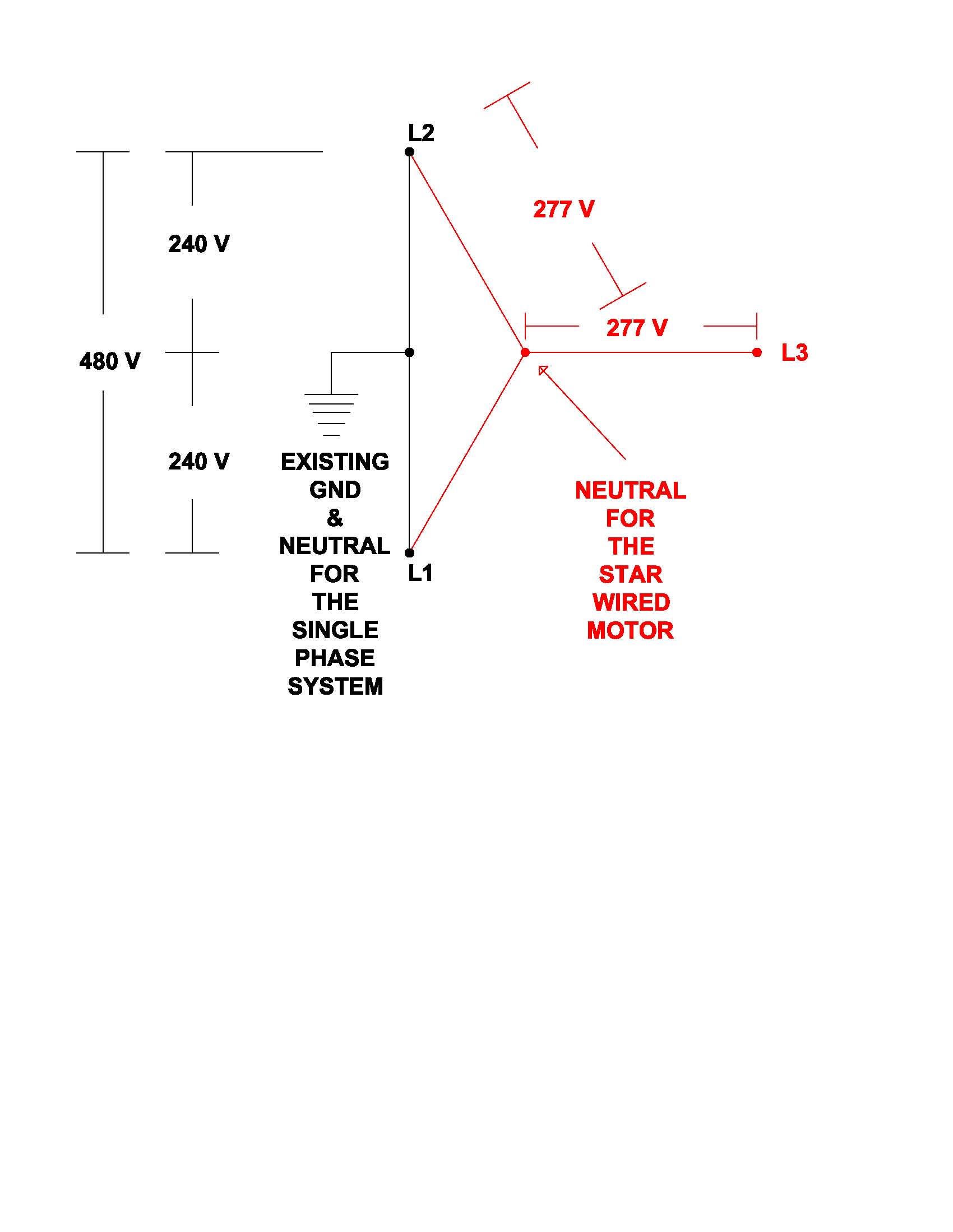
My vector math tells me if you apply 480 volts to the L1 and L2 terminals (or the L2 and L3 terminals, or the L1 and L3 terminals) of a star
connected motor you will get 277 volts across the motor winding between the L1 terminal and the "neutral" of the star and 277 volts
across the motor winding between the L2 terminal and the neutral of the star (480 divided by the square root of 3). Are using some different kind of vector math than I am?
junker2,
It's called "empirical evidence" But you believe what you want to believe, it doesn't change reality.
I'm sorry if I jumped on you, the reason is because from half a world away, you are trying to tell me that what's on my bench is only a figment of my imagination.
Rob.
Here is the vector diagram when you apply 480 volts single phase to the L1 and L2 terminals of a three phase 415 volt star wired motor.
Attachment 16975
Please note that you have 277 volts across each motor winding while the idler motor is running.
It has already been suggested by Frank S that you would need 415 volts.
Quote:
"Originally Posted by Frank S.
To run a RPC (rotary phase converter in Australia, if you are in rule areas you could have what some call 2 ph 480 which would be to hots and neutral. but most areas without 3 ph or the rule areas with 2 ph there is only 1 240v line with a nuetral. to make a RPC run in those places a transformer would be required to make the 415v split phase L1 +N for input then tap at 175-0 240 +415 nominal for output. then connect the 2 output line to the PRC and the cap bank for starting and a module of thyristers for full balanced true sine wave 3p output.
Here is a commercial site selling their product but the information there will give you an idea of how to go about it
3 Three Phase Power Converter Australia converts single phase to three phase.
I think if it were me needing to do this I would buy MR nhengineer's plans then go from there adding what might be needed and contacting him for assistance."
Your cheapest alternative is to re-wire the 3 phase idler motor and the 3 phase load equipment to accept 240 Volt 3 phase delta. Then you will not need a transformer. There are multiple videos of this scheme in operation on you tube.
What empiracal evidence are you referring to Rob? Your power calculations make no sense what so ever to me. Is it 10 amps three phase at 415 volts or 10 amps 3 phase at 240 volts and what is the power factor?Quote:
"Originally Posted by old kodger
Rhengieer,
I thank you for your effort, but now you see what I mean when I say, in Australia most of the options to date are totally uneconomic, for instance, I need to power a 3 phase mig welder which is name-plated at 10 amps per phase which is about 7.1kw at 230 volts. If a 3hp transformer is likely to cost $450 US that's around $600 AU, and I might need two...$1200 plus freight, and as I mentioned before freight from the US to AU needs the surrender of ones first born, I would not be surprised to find that the freight exceeded the initial cost of the transformers. Also 3hp would woefully inadequate, I need at least 10 amps per phase, for a overload margin, maybe more.
So at a potential cost in excess of $2400, a second hand 3 phase generator is starting to look a lot more realistic.
I thank you for all your effort, and indeed to all the other contributors to this thread, but unless I can find a way to control a synchronous motor acting as a generator, I have two options:- buy a generator or attempt to rewire the welder to run on single phase. Incidentally, I'm informed by the manufacturers of the welder, that the configuration internally is actually three separate transformers feeding a bank of full wave bridges, so it could be possible.
If anyone is interested I'll keep you informed.
Rob."
Good luck with your project
Junker2
Junker2,
The reason you can't make it seem to work, is because your circuit schematic is wrong.
The ground between the two 240 volt "phases" should be connected to the junction point of the star. What you are trying to do is connect the circuit up delta, and you can only do that with a rotating supply (genuine 3 phase 120 degrees displaced), at which point you will find 415 between any two phases.
The question of "my maths" is one of terminology. All phases in Australia are 240 volt between hot and ground, therefore, 3 phases are 3 lots of 240 volt 120 degrees apart. In the instant of the welder, name plate amps are "10 amps per phase" and since the welder does not require a rotating supply it is in effect a star wound device (each phase 'pulls' 10 amps) giving you 30 amps across all phases. However all three phases after transformation, ultimately feed into a full wave bridge, thereby giving the result of one big transformer producing DC output.
This could be done with one big transformer but it's not the economic way to go (wire sizes, breakers etc,) so split the load between 3 phases and recombine after transformation to achieve final output.
At this point however I must desist, because this thread is supposed to be about rotary conversion of single into 3 phase, we are no longer talking about that, so have in effect hyjacked the thread.
Rob.
To Rob AKA: old kodger,
It is obvious you do not understand 3 phase power systems. The welder does require a three phase "rotating" power supply to function correctly at name plate rated output. The correct power calculation for a three phase system is "volts" times "amps" times "square root of 3" times "power factor". So if the imaginary "welder" nameplate data states 10 amps at 240 volts at three phase it would consume 10 times 240 times 1.73 times some unknown power factor that you can not specify since you have no clue what a "power factor" is. The absolute maximum consumed power for the welder would be 4157 watts. The current does not flow from the 240 volt point of the star to "ground".
In the 480 volt single phase diagram I uploaded previously, if you connect the single phase ground to the neutral of the 415 volt star wired idler motor the rotary phase converter will NEVER function correctly. In the first place you need to apply a 415 volt single phase voltage. The mechanical placement of the star wound motor windings are 120 degrees apart on the stator of the motor. The neutral of the star wound motor has to "shift" relative to the existing ground of a 415 volt single phase system while the idler motor is rotating. If you hardwire the existing ground to the neutral of the idler motor you are electrically exciting two of the motor magnetic pole pairs with a voltage that is 180 degrees apart.
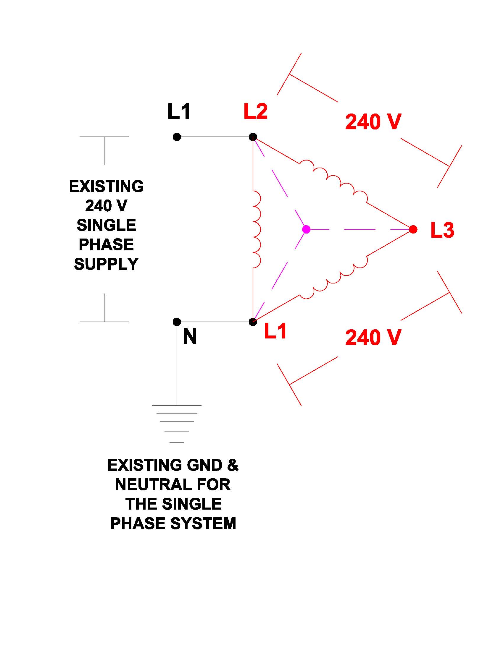
For your enjoyment I have attached a diagram for a 240 volt delta connected idler motor setup. The magenta colors show the "virtual" neutral point that does not actually physically exist (this was explained by Paul Alciatore assuming you can understand the electromagnetic theory involved).
Attachment 17004
Good Luck
Junker2
Yeah *sigh* but I never implied a pull rope would not work. Before running your mouth, Junker2, about something you have not even seen, buy the damn plans and educate yourself..... or are you too cheap?Quote:
Originally Posted by Junker2
As I may have stated before, :smash:Quote:
Originally Posted by old kodger
Junker2
I'll take your points one at a time (as far as possible)
(1) I have contacted the manufacturers of the welder, AND IT IS THEY who said that the machine is simply three individual transformers of 240 volts, and that they
use 3 phase supply to reduce cabling and contactor sizes
(2) It happens that I DO know what a power factor is And in this instant, it's value. I simply forgot to include it in my post (.8)
(3) If it pleases you to attempt to intimidate me, then I bow to junker2, God of electricity.
If you can wire the welder in a 240 volt three phase delta configuration you should have an economically feasible solution to build an RPC using a 240 volt delta motor as the idler. That is what your original complaint was about right? This does not require the unnecessary expense of a transformer. If it were me building it, I would use a bank of start capacitors and drop out relay instead of a "pony" motor for starting the idler. Reason being no extraneous moving parts, no belts/pulleys, and no fabrication expense for mounting it.
i thought u quit nhengineer
did u study engineering or business at that eastern college?
cause all u want to do is sell me your inferior plans. I might review your plans for a nominal fee. coming from a REAL engineer
It seems you do not want to discuss any of the technical problems
Gee , i wonder why?
nhengineer is not a REAL engineer
Apparently he is a dumb ass
Junker2
I fully agree any one bragging about there titles are just wanna be's or maybe he needs the money
This is quite true, but, as has been pounded into me several times, transformers, at least at this power level, are apparently very expensive in Australia.
AND, this is a discussion about converting 240V, SINGLE phase power to run a three phase motor, not using TWO 240V phases/lines for that purpose. If, as was shown above, you connect a single, SINGLE PHASE line to two of the phase inputs (A-B and B-C for example) of a three phase motor, you will either have a short circuit (you would never actually do this) or ZERO Volts across the combination (A-C), not 480 Volts. In either case, the three phase motor will not run, even if you start it with a pony motor or rope. This is clearly not a possibility.
Since Australian single phase power is 240 Volts, I would think that their three phase power MAY be three of those single phase lines or three, 240 Volt lines that are 120 degrees out of phase with each other. If that is the case, then wouldn't the most popular Voltage for a relatively small three phase motor there be 240V, three phase? With zero experience in Australia, I may have that wrong so any Australians please feel free to correct me on it. But if that is true, then Y connected, three phase motors found there would be expecting no more than about 416 Volts across any two terminals. And I would think that delta connected ones would also expect about 416 Volts. In either case a single, 240 Volt phase could safely be connected to any of them. if it does not run, I would remove power after a few seconds to prevent heat build-up, but other wise it will be safe; no insulation breakdown, no arcing. In fact, the hard part may be finding a three phase motor that will run on a lower Voltage, not a higher Voltage one.
Also, I may not completely agree with everything that nhengineer has said, but I do not think it is helpful to use personal attacks. I don't recall exactly what he may have said his educational background was, but a degree is not everything. Experience is a big factor, probably a more important one. In my case, I do have a degree, but not an engineering one. It is in physics, which includes electricity and magnetism. So I do understand E-M at a very fundamental level. And I also have a career of experience in TV engineering which may be oriented towards electronics, but many of my employers expected me to design, install, and fix almost anything that was the least bit technical in the building or around it. I once had to solve a problem with rain water getting into the boss's office. Repaired door openers. Did roof work. I even had to fix toilets in some places. And perhaps more pertinent, HVAC work was present in every job I ever had; sometimes only on an emergency basis, but always there. Ever try to get an AC technician up a mountain on a Sunday? Heck, you couldn't even get them on the phone.
One thing that my experience has taught me is that I CAN be wrong. And I try to watch for it all the time.
Anyway, give the guy a break. Do give your arguments here, but also listen to his and to others. And think about them before answering.
I can't resist another comment on that transformer expense thing. Someone above said that it would be better to buy a motor-generator instead of using a transformer. Is this really the case? How, at the SAME power level, can a motor-generator cost less than a transformer? In the motor-generator, BOTH the motor and the generator would have to have at least as much and probably more copper and other metals than a transformer with the same power rating would have. And there are moving parts that require things like bearings. There are more parts in the motor-generator and it's assembly is more involved. That easily adds up to more than twice the metal and therefore should be more than twice the cost of the transformer. Doesn't it? Is there a special tax on transformers in Australia? Or was that poster ill informed? Or is this the business opportunity of the century for an Australian entrepreneur to make or import transformers?
Quote:
Originally Posted by old kodger
Paul A.
It was I who made those comments, and I will agree, without verification.
So, without emotion, here are the answers to your queries. I did this research only two or three days ago. a transformer to give 480 volts center tapped and capable of 8kva,(I asked for a ball park figure) was at least, and upward of $1650.
Some three months ago I bought a second hand, 5kva unity pf diesel generator for $450. now I'll be the first to agree that these two things are not quite the same, but upping the generator output to 8kva is not so big a jump, so whilst I cannot give you hard and fast costs (they are after all second hand), you can see why I might have made those comments.
Rob.
Paul,
Oh, by the way, I'd have to buy the idler motor as well. Checked that one out as well, nobody wants to give one away, if it works,they want to sell it as a going concern.
Rob.
I know the way the draw shows is simple use sign phase motor to turn a three phase motor after up to speed give power the main motor and disconnect the sign phase motor.
I do not know if he ever had any engineering ???. He does not sound like a engineer.
Dave
Quote:
Originally Posted by Junker2