junkers2,
I tire of this, either take my word for it or GO AND DO YOUR OWN RESEARCH into three phase motor connections. I'm sure American motors would be the same as Australian motors except for the different potential.
Old Kodger.
junkers2,
I tire of this, either take my word for it or GO AND DO YOUR OWN RESEARCH into three phase motor connections. I'm sure American motors would be the same as Australian motors except for the different potential.
Old Kodger.
That statement is not real accurate. Most 3 phase motors in the US are 9 lead motors and are convertable between 230 volts (low voltage) or 460 volts (high voltage). See attached diagram for the connection schematic.Quote:
Originally Posted by old kodger
................
................
I'm sure American motors would be the same as Australian motors except for the different potential.
Attachment 20996
Please note these 9 lead motors are fixed at the factory as either a series/parallel wye or a series/parallel delta. Now if the motor is a 12 lead motor we could wire it as series or parallel in a star or delta configuration with multiple voltages (230/400/460). usually the only wye/delta motors in the US are large horse power units designed for wye/delta starting to reduce the inrush starting amps.
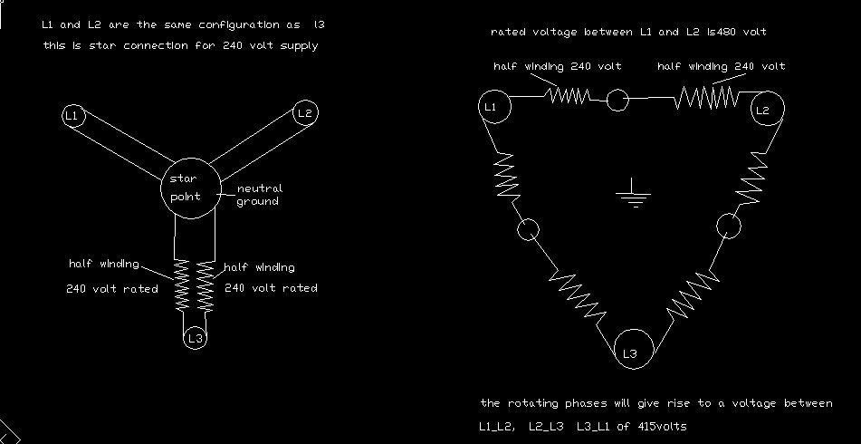
If you have access to a 6 lead 3 phase 240 volt delta/415 volt star idler motor you should look at this youtube video:
https://youtu.be/TXVlIU73yFg
where "RODALCO2007" starts the motor in delta with single phase 230 volts and swaps it to star to generate 400 volts directy from the 230 volt single phase line, no step up transformer needed. I don't know how much power the idler motor will output when configured this way but it is the most interesting scheme to get 3 phase 415 volts from a single phase 240 V supply without a step up transformer.
To Frank SQuote:
Originally Posted by Frank S
He wouldn't the center tap of the secondaries would be grounded to earth leaving 2 hot wires each having 240 volts or most probably 230v with those he could connect to 2 legs of the 3ph idler motor, and connect his load to all 3 of the legs. A bank of capacitors would help to smooth out the 3 ph out put but not entirely necessary if he has a fractional hp single ph motor to spin up the idler motor.
................
................
If you connect the idler motor as you describe above with 480 volts SINGLE PHASE across two terminals of a three phase star wired motor rated for 415 volts (if wired for three phase delta it would be rated for 240 volts) you will be applying 277 volts across each idler motor winding, not 240 volts!
It appears both "old kodger" and "nhengineer" do not understand how a three phase 240 volt delta/415 volt star motor works much less how to connect one.
Yup, that's right. I don't know nothing. How about you Rob?Quote:
Originally Posted by Junker2
Nah!
I've known nothing for about 60 odd years
Rob.
Mr junkers2,
I apologize for my lack of command of the English language sufficient to communicate to you in post 191 how electric motors are constructed in Australia. So, since words fail......see sketch attached.
However, a reply to this post is not required as I will no longer respond to your comments. I simply refer you to my previous post suggesting that you design and build a rotary phase converter to run on two wire 240 volt single phase.
Regards, Rob.
Attachment 21073
Hi Dave.... Sent you pm. I clicked download link too many times. I need it reactivated.
Thanks!
Medmike,Quote:
Originally Posted by Medmike
Write to Jon at jon@homemadetools.net and tell him what happened. He'll straighten it out.
All set Medmike - I've reset your download count so you can download the plans a few more times.
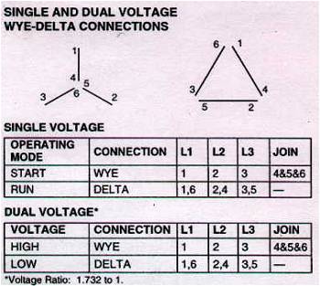
Based on the diagram you uploaded of how you would connect a dual voltage 240/415 volt three phase motor it is obvious you do not have a clue how a 3 phase AC induction motor works, how to wire a 6 lead dual voltage 415 volt star/240 volt delta motor, or the commonly used nomenclature for 3 phase power. The figure on the left of the diagram you uploaded would theoretically work for your imaginary 9 lead 3 phase motor but as wired it would need the utility power to be a 240/415 volt 3 phase system. Meaning the line to neutral utility voltage would be 240 volts and the line to line utility voltage would be 415 volts. The proper description for utility power is the the line to neutral voltage, the line to line voltages, and the number of phases. For instance just to name a few here in the US we have single phase 120/240 volt service (used in residential or very light commercial service), 3 phase 120/208 WYE (used in light commercial and light industrial), 3 phase 120/240 DELTA (used in light commercial and light industrial service), and 3 phase 277/480 WYE (used in heavy commercial and heavy industrial service). Most of these utility voltages are "inherited" at the property location when an entity acquires ownership of the location due to the high expense of installing new electrical equipment. The figure on the right of the diagram you uploaded is a figment of your imagination. There are no motors with a connection scheme like your diagram depicts and it has no factual basis whatsoever in AC induction motor theory. Your diagram tells me just how much "knowledge" of three phase systems you posses. For your education I have attached a REAL wiring diagram for a 6 lead wye/delta motor (AKA star/delta).Quote:
Originally Posted by old kodger
Mr junkers2,
I apologize for my lack of command of the English language sufficient to communicate to you in post 191 how electric motors are constructed in Australia. So, since words fail......see sketch attached.
However, a reply to this post is not required as I will no longer respond to your comments. I simply refer you to my previous post suggesting that you design and build a rotary phase converter to run on two wire 240 volt single phase.
Regards, Rob.
Attachment 21207
Attachment 21208
Instead of spending your time teaching your relatives how to suck eggs perhaps you should invest some time in learning about three phase power systems, AC induction motor theory and basic transformer theory so you could maintain a reasonable conversation about rotary phase converters.
As you have adamently stated the utility voltages in Australia are 240/415 volt 3 phase for commercial properties and 240 volt single phase for residential properties. What you have not stated is what voltage you want your idler motor to produce in your rotary phase converter (RPC). I assume you want to generate 240/415 volt 3 phase so you do not have to rewire/reconfigure any of the 3 phase equipment you are powering. Although if you can rewire/reconfigure your equipment to accept 240 volt 3 phase delta that would be the cheapest option since no step up transformer would be required. Nor have you completely listed ALL the data on the nameplate for the welder and any other 3 phase equipment you want to power with the your RPC.
regards
Junker2
I'm done with this thread.
Frank S,
So am I.
Me three. :agree:
Could I trouble you for a quick question? I have acquired a 1950 era American Tool Works Pacemaker lathe 16x54. It is powered with a 10hp 3 phase motor and i have yet to trace all of the 'thingies' in the electrical box to know what is what as it has 5 wires in the cord the previous owner cut to keep the end. I have used rotary phase generators for over a decade as my mill is 3hp 3phase and my cincinatti pressbrake is 5 or 7hp (just can't remember at the moment) 3 phase and 3 phase isn't available on the farm. With all of that said, I've always been told a rule of 1/3rd, generate 1/3 more hp 3 phase than required to have the power to power the machine. My first generator was an old 5hp 3 phase that was the size of a small car engine and I'd pull start it with a short rope. All was fine until I got the new to me Cincinati Press Brake and I needed more power, it would blow my fuses before the pressbrake could get up to speed. I came across a 10hp 3phase for around $25 and I rewired this time with pony motor.. Now I have a 10hp lathe to get going.. I first aquired a 45hp GIANT 3 phase motor I thought was a good idea, I was informed i had made a mistake and I have yet to.... Last week I found a nice 15hp 3 phase motor I'm hoping can power the lathe. What would you suggest? Is the 15hp going to have the power to get the old girl (lathe) spinning, or should I?
Jeff
Jeff I can't speak for MR. rhengineer but I would say that 15 hp 3 ph motor started with a 3/4 to 1 hp pony motor such as his plans describe would be more than adequate to start your 10 hp lathe. However there are other ways you mentioned your generator is is already a 10 hp with pony motor start you might try adding an additional 5 hp 3 ph idler motor to your existing unit just wire it in with a contactor and switch it on once your generator is running adding 70 to 100 Uf per hp run capacitors between 1 leg of the input and the 3rd leg of the generator helps to smooth out the phase angle as well
Attachment 21878
My generator is a 3 hp cap start cap run no pony motor unit that I run my 3 hp Leblond on I really need a 5 to a 7.5 Hp motor on the lathe but haven't gotten around to building a larger generator yet but I have on occasion ran both my lathe and my 3hp mill at the same time on the single 3hp generator by starting the lathe first. I also find that if I let 1 machine run idle I can make heavier cuts with the other than I could by having only a single machine running.
Another thing you could do unless you are really trying to make monster hog off chips would be to resize the motor on the lathe to 7.5 hp as I said my Le blond is running on 3 hp but it is also a 17" swing lathe
I have a set of rhengineer's plans and will be constructing my next generator bases in part on his plans with some additions of my own
Hi Jeff. The 'rule of thumb' you mentioned is what I use as well. Since the idler only has two hot legs, it's only capable of 2/3's of its nameplate HP rating; perhaps even a bit less depending on age and efficiency. I would recommend you add together all the 3-phase motors that will be running at the same time (maybe there is only one), multiply that value by three and then divide by two. That puts you in the ball park. Then pick the next higher standard HP idler. That gives you the absolute minimum HP you can use.Quote:
Originally Posted by JeffEck
The multiple conductor cord may indicate that the motor set-up is reversible. Any 3-phase motor can be reversed simply by switching any two of the three output conductors FROM the 3-phase converter. This can be accomplished using a 'two pole - two throw' toggle rated for the load. Remember to let the load motor idle down to 0 RPM before switching. Write back if you need a schematic.
I hope the above is helpful.
David Lee
Gents, thank you for your responses. I may be daft, but am I understanding that I can run more than 1 idling generating 3 phase motors in the system to even out the phase out-of-sync? I think I understood the adding of all the motors that could run at the same time and generate from that level of hp requirment 2/3 rule.
I would appreciate any schematics/idiot guides you have to offer. I have a 3 or 5hp #22 Buffalo Forge drill press, Bridgeport Clone 3hp, Cincinnati 35Ton press brake 5 or 7hp, and now my new lady (my wife is understanding of a mans needs) 10hp Pacemaker lathe.
I am also in process of semi-automating my Straight guillotine bandsaw, using limit switches, contactors, momentary push buttons to make the hydraulic lift go up to an adjustable height to make for quicker operations and less over lifting or thinking on my employee when they are cuting many parts of the same sized material, it will move up and down on a shaft collar running on the dual posts that hold the saw 'head'. Also adding built in lighting and control of coolant pump to be automatic with the saw motor. The last part of that system is a switch to manual so that if something breaks you can still just flip a couple switches and it will still work..
Many thanks!!
For the record, I did not recommend that. I do not know if it would work out or not.Quote:
Originally Posted by JeffEck
Some food for thought. if you already have 1 rotary converter with or without the starting assistance of a pony motor you can parallel in idler motors till kingdom come as long as your line amperage is sufficient to handle the per phase load amperage of the equipment which is going to be run off of the converters.Quote:
Originally Posted by nhengineer
I often use the motor on my end mill as a booster idler for when I need tr run heavy loads on my lathe and vice versa. I do this because my converter is the same size as the motors on the lathe and the mill which means either must be started under no load. Ideally I would have a 5HP converter.
Here is a chart which shows the maximum amount of installed HP which can be run on a given sized converter as long as all motors are lightly loaded and not started at the same time. the chart also describes how multiple converters may be linked together for starting larger motors
Attachment 21883
If I had some large capacitors I would be tempted to see if I can get my little 3 hp converter to start an 8 hp inverter rated motor that I have and allow it to run as an idler in parallel to see if I would have sufficient power to rower up a 240 to 480 v transformer that is needed to run my 7.5 HP Cleereman index drill now that the electric co has installed new 2 ought feeder lines to my meter as opposed to the old #4 AWG lines I had before. I might have to add a 3 hp idler before the 8 hp but that would or should according to the chart give me the equivalent of a 14 HP converter
I went back and reread it, I totally got both responses all mushed in my head... Been a long day, I started at 2:45 am as I couldn't sleep last night, although most days I get to the shop at 4am... Early bird, worm, yeah I'm still trying to find the worms...... Thank you for correcting me, makes much more sense when given a second read and it soaks in...
According to Phase-A-Matic, Inc.Quote:
Originally Posted by Frank S
Due to the high in-rush current required to start a motor (5 to 10 times the normal running
current), most applications require sizing the HP of the Rotary Converter 50% larger, or
more than the horsepower of the largest motor, or any combination of motors started at
exactly the same time. The first motor started, if not running heavily loaded, generates
additional 3-phase power back into the circuit. You can then run additional motors provided
they do not run heavily loaded and are not started at the same time. A maximum of up to 3
times the HP rating of the Rotary Converter can run at the same time - if not heavily loaded,
and not started simultaneously. For example, a 30 HP Rotary Converter potentially could
run motors totaling up to 90 HP.
If you are going to have to try and run any 3 ph CNC equipment you need to also have a voltage stabilizer which is as near as I can ascertain is something like a static phase converter and a bank of capacitors tied into the rotary converter.
Thank you, David and Frank, I am going to do some experimenting and see what happens.
do these plans only show using a pony motor to start the idler motor ?
The plans are complete including the schematic and all the necessary purchased parts information. If you buy the plans and you're not satisfied, Jon has a 100% guarantee. Of all the converter plans sold, no one has asked for a refund yet. If you find something not to be clear or missing, contact me here and I'll get what you need.
Thanks, I might be being picky but, I don't want to use a pony motor to start the idle motor. Was hoping your plans included using start caps to get the idle motor started. I've also seen plans that include a time delay and a relay to take the start caps out of the circuit. I'm just a dumb guy farting around in his garage so I can't figure everything out on my own. I need a wiring diagram for dummies :PQuote:
Originally Posted by nhengineer
A guy who bought my plans used a rope around the converter motor pulley instead of a pony motor. He told me it works slick but that was many years ago.