I have several 1/3 Hp 120 V I believe i still have them. I will sell one PM me if interestedQuote:
Originally Posted by old kodger
I have several 1/3 Hp 120 V I believe i still have them. I will sell one PM me if interestedQuote:
Originally Posted by old kodger
WOW A lot of reading and arguing I don't currently have the link but there is another phase converter no one has mentioned it uses a single phase transformer with a 220 volt primary (or 240 volt as you want to call it) and a 3 wire center tapped 120-0-120 secondary and the secondary side is hooked to make a high amperage 120 volt secondary that has 1 lag tied to the primary in a way that produces about 360 volts at the open end of the 129 volt secondary and the other end of the primary that power is then fed through capacitors (calculated to the amperage requirements of the 3 phase load) the rating of the transformer to the motor HP was about 1 KVA per HP Nothing rotating and FULL rated starting torque I bought the book but have not made that type of converter yet although I have accumulated all the parts to do so I bought the book on AMAZON Gary
Where was it "shown above" for the connections you describe?Quote:
Originally Posted by Paul Alciatore
You would connect a single, SINGLE PHASE line to two of the motor terminals (A-B OR B-C OR A-C) of a three phase motor. It doesn't matter if it is a star wired motor or a delta wired motor as long as the applied voltage corresponds to the motor rated voltage.
All the RPC designs I have seen are similar with respect to one thing. After the idler motor is brought up to speed they all connect a single phase voltage of an RMS amplitude that corresponds to the motor nameplate voltage rating to two out of the three idler motor terminals. If you have a 3 phase, 240 volt rated idler motor you apply a 240 volt single phase voltage and can generate a 3 phase 240 volt supply. If you want to generate a 415 volt three phase supply you would need to apply a 415 volt single phase voltage to a three phase idler motor wired for the 415 volts. If you only have a 240 volt single phase voltage available you could step the 240 volt single phase up to 415 volts single phase to generate the 415 volt three phase supply with the 415 volt three phase idler motor. For some reason old kodger and nhengineer believe the 415 volt single phase needs to be 480 volts single phase to apply to the 415 volt idler motor. You could also take the 240 volt three phase output of the 240 volt idler and use a three phase transformer to get a 415 volt three phase supply but transformers cost money, especially three phase ones or three single phase ones wired in a three phase bank.
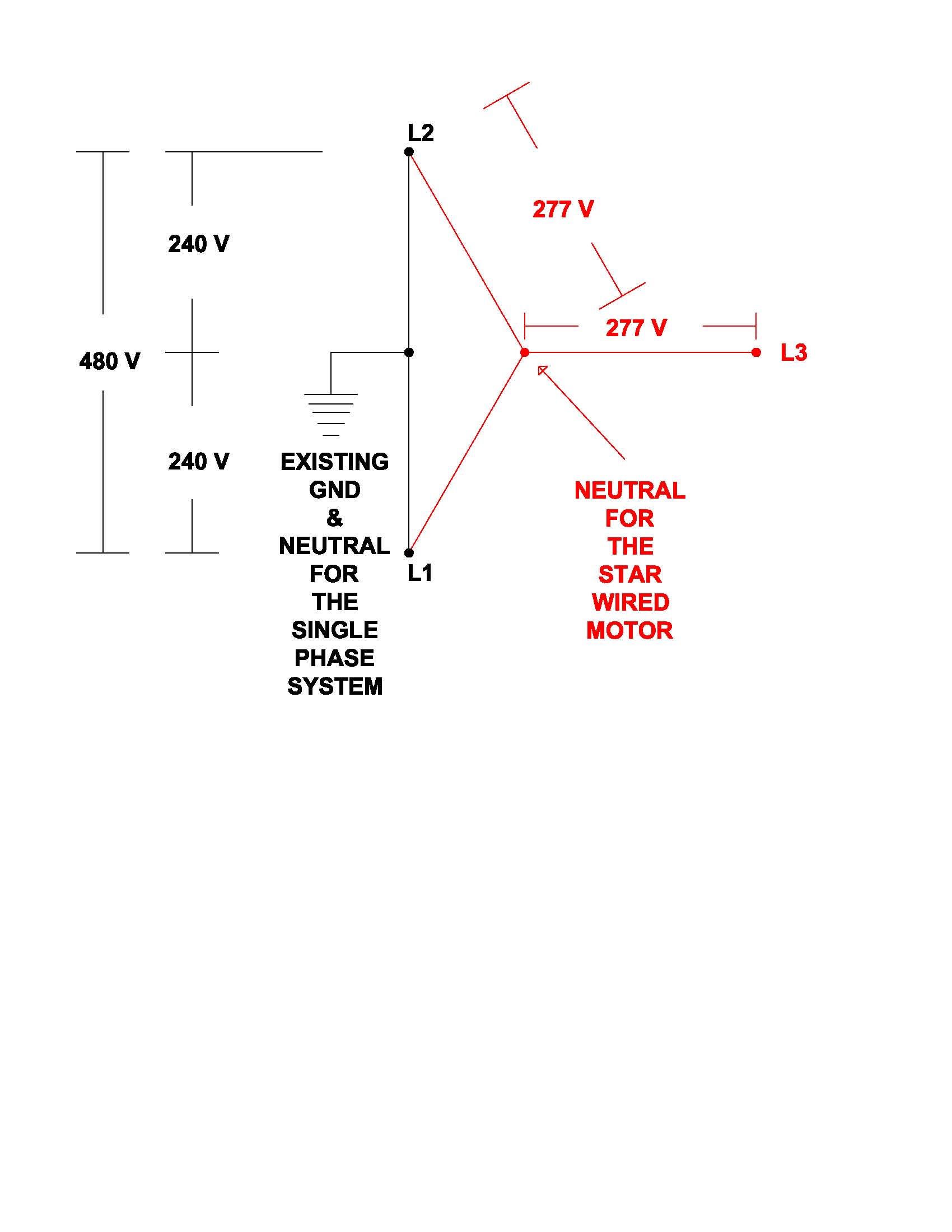
The first diagram I uploaded:
shows the error in applying a 480 volt single phase voltage to a star wound 415 volt three phase idler motor.Quote:
Originally Posted by Junker2
This is the post where nhengineer claims to have studied power distribution.
Based on nhengineer's "design calculations" so far, I wonder exactly what they teach there.Quote:
Originally Posted by nhengineer
Almost ever one that has had single phase dream of just using a transformer
The close it can get is simple three phase motor converted to single phase and using the third leg for the three phase (rotary type transformer)
This why most MFG of converter use a simple start cap and relay The converts a three phase motor to single for few seconds now you have a rotary type transformer
Good luck
Dave
Quote:
Originally Posted by Junker2
Junker2,
I guess I was referring to the diagram in your post #146 where you clearly show two 240V phases with a ground at their common point. You show these two adding up to 480V but you do not show any transformer. And they are connected to two terminals of a three phase motor in that diagram. My point was that if a building had only single phase, 240 Volt service, as a person in Australia would typically have, then there is no way to get 480V (or was it 415V?) from that without using a transformer. And those transformers apparently are prohibitively expensive. Perhaps I misunderstood, but you seemed to be suggesting that a single 240V, single phase feed could be hooked up in that manner to produce 240V.
I personally think this discussion is getting a bit ridiculous. We are, or at least we originally were, discussing the use of nhengineer's design in Australia. But I and apparently most of us have never even seen his plans or even a circuit diagram of the design. So we have no idea if it is or is not possible to use it there. He seems to think that it is not suitable.
Quote:
Originally Posted by Junker2
Here is where nhengineer realized there needs to be two hot leads (out of phase with each other) with reference to earth ground for his present design to work.
Quote:
Originally Posted by nhengineer
Somewhere around here is where old kodger suggested using two phases of 230 volts 180 degrees apart.
Quote:
Originally Posted by old kodger
And here is where nhengineer confirmed that old kodger would need two phases of 230 volts 180 degrees apart.
Quote:
Originally Posted by nhengineer
Quote:
Originally Posted by nhengineer
Now why would you want to buy an expensive transformer to get the two 230V outputs a half phase apart that would create (kind of) a 230V 3-phase (supply) suitable to run your 230V, 3-phase motors with reduced horsepower output (83.3% of the nameplate rating) when all the other RPC designs use a 230 volt (240 volt) idler motor to generate a "full" power 240 volt 3 phase supply?
I assumed they wanted the "480" volts to generate a 415 volt supply from a 415 volt star wired idler motor.
Quote:
Originally Posted by Paul Alciatore
Paul,
Yes, the 480 volts is generated from a transformer configured as they are discussing above. I uploaded the diagram in post #146 to show that if the 480 volts was connected as shown in the diagram the actual voltage across the motor winding would be 277 volts, NOT the 240 volts that the motor windings are rated for.
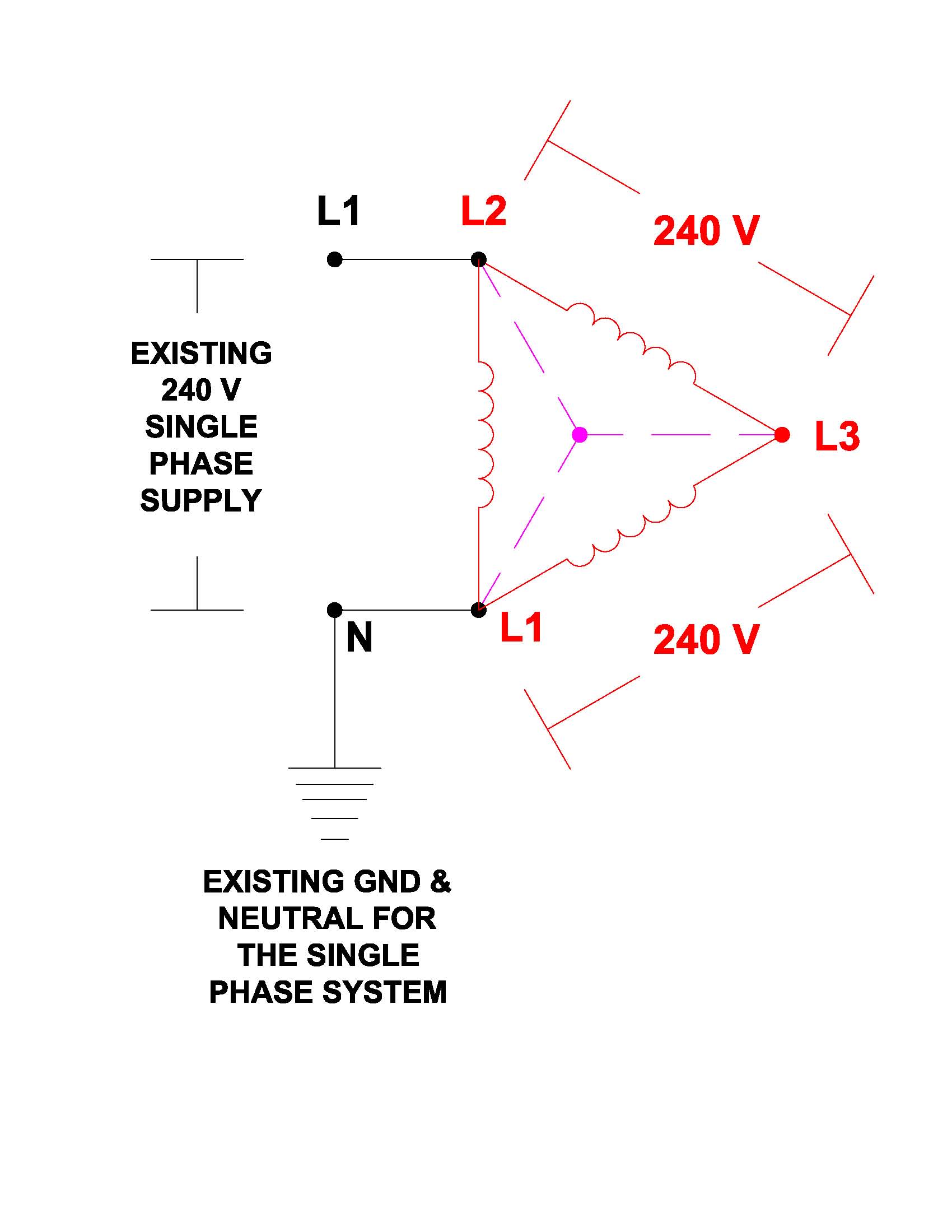
This post:
Quote:
Originally Posted by Junker2
shows how to connect a 240 volt single phase system to generate a 240 volt three phase supply WITHOUT THE NEED FOR ANY TRANSFORMERS.
I agree Paul, At this point, this thread appears to be a big circle jerk.
The one thing that caused this thread to travel down the road top perdition is the fact that there are folks all around the globe with differing electrical power services available to them, plus the fact that not everyone understands that when something is written up or explained it can mean the nominal voltage, as with the term of single phase. In the USA single phase 220/240 volts requires 2 hot lines of 120 volts (nominal) in other places this is done by a single hot leg and the neutral. In many places such as Europe or in particular the Middle east 3 phase power is supplied to many homes in the form of 415v across any 2 of the phases
While I was working in Kuwait we often installed overhead doors made in Denmark that were powered by small 3 ph motors but only used a single hot leg and the common. this was accomplished via a very compact box which contained a small center tapped transformer and a couple of capacitors and not a whole lot else except for maybe a few resistors and a 5 amp fuse and a reversing switch.
I do onw a set of rhengineer's rotary phase converter plans and although his method of construction differs from the way I made my RPC years ago they are a valid set of plans. But no as they are written up they do not address differing voltages or energy production methods around the world. any more than a friend of mine who lives in New Zealand on another form who a long time ago made his own buck and boost transformer would have worked as made in the USA However he later created a spread sheet calculator which if a person understood enough about how electromagnetic currents are created could build their own
I've posted a few times on this thread of how a solution to achieving 3 ph from 1 ph could be accomplished, as wqell as a couple of others who have posted as well. This is not to say that my way or another's way is better or the only way they are simply a means to reach a suitable outcome.
When it comes to a RPC for small ones I prefer to simply add the required amount of capacitors to the idler motor when the become larger say over 7.5 HP the addition of a pony motor to serve as a means to start the idler motor turning reduces the inrush current of the locked rotor condition call it reducing amperage spike. However I still prefer to have a bank of capacitors across the phases of the idler motor to smooth out the 120° 3 ph offset from the 180° of a 2 hot line single phase.
You still need a way of creating 2 hot legs though in order for any 3 ph motor to be started and run even with the addition of capacitors or a pony motor, no matter what the desired output voltage is to be. The 1 exception might be and I say this only becaus I have never had the opportunity to try it, would be a motor with 12 or 18 wires, instead of the more common 9 wire motors
Hi Frank S,Quote:
Originally Posted by Frank S
Thank you for your input. Everything you have written is correct. I have never implied it was the ONLY way to run a 3-phase motor from 2-phase service but my RPC design has worked for me running my Bridgeport, lathe and 7-1/2 HP compressor since 2012.
I have refused to get into a urinating contest with the trolls patrolling this thread and, by your writing, "...I do own a set of nhengineer's rotary phase converter plans and although his method of construction differs from the way I made my RPC years ago they are a valid set of plans..." you may now be a victim of their venom as well. Honestly, I've found their exchanges quite entertaining. It is interesting to note that they have never even seen my plans yet they freely criticize them.
For your edification, the edification of sincere contributors here and the edification of prospective owners of my plans, at the time I created them, I had no consideration of helping builders other than those in the western hemisphere. It simply did not occur to me. Now that there have been international inquiries, I intend to amend the booklet to include possible uses in former British Crown colonies (India, Japan, New Zealand and others) with the help of our Rob Candy (Australia).
In Rob's case, my research so far indicates that just the addition of a properly configured transformer would provide the required 2-phase service to the idler motor but presently I have been too busy designing and building a lift table to devote my resources to that endeavor.
Thank you again for your valued contributions here.
Best regards,
David Lee
Frank S
BRAVO!!
Rob
I made a phase converter 20 years from plans I found on eBay, I used a 50 dollar 10 HP motor it worked for 10 years then I started adding bigger machines 15 HP and 10 HP. I bought a larger one with about 8 capacitors and have been very satisfied. If this book covers larger motors it is a steal at 12.50.Quote:
Originally Posted by Jon
Size is relative. This is a generic instruction booklet. There's a chart that shows what size idler motor is recommended for the load. Basically, since were only using two legs of the three-phase you have only 2/3's of the load capacity. You would need to multiply the load by 1.5 and pick the nearest larger HP motor available as the idler. For example, for a 7-1/2 HP load you would need 7.5 * 1.5 = 11.25 HP idler. Since that size does not exist, go to the nearest larger motor available which would be 15 HP.
The link following is a good reference. http://www.sprecherschuh.com/downloa...chart_v206.pdf
Quote:
Originally Posted by old kodger
Clarification
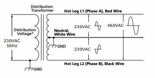
Actually here in the States we do not refer to this as two phases, its just single phase... Its 208-240 VAC depending on the transformer providing the service to the customer... Both Residential and Industrial the single phase is provided with a center tap off the transformer, this leads to 120 vac legs, that are hot with respect to neutral. Neutral is also earth ground at both the transformer pole and at the circuit breaker load center... But the hot legs are always opposite polarity to each other so they have a maximum voltage of 208-240 vac when connected across the two hot legs of the transformer secondary output... The neutral wire or center tap, carry's current based on the loading in each hot leg, if one hot leg is carrying more current than the other, this will cause a flow of current in the neutral or center tap wire.
Sincerely,
Ron
Ron,Quote:
Originally Posted by Mcgyver28117
Thanks for that clarification. I'm curious though; is our 208/240 actually 2-phase? I've had some folks refer to it as 2-phase but I haven't been able to confirm that it is. It would depend on how the transformer was wound wouldn't it?
Well it kinda goes like this, people become familiar with 3 phase and associate it with 3 wires, then they later see 2 wires and say hey it's 2 phase... but that is not how it works, nor what it means... with 3 phase their are 3 sine waves 120 degrees apart, if one has a 3 channel oscilloscope, this can be see as the some wave between legs a to b, leg b to c and legs c to a... with only 2 wires, we have only one sine wave or one phase, the center tap only provides a voltage divide by 2 function, stiil just one sine wave, because if we have an equal numbers of devices on the leg a to center tap and leg b to center tap, we have no current flow through the center tap... It's just one phase...
Ron
Two phase? Well it is a bit more complicated than that. And it is embedded in tradition.
Three phase is not three phase because it uses three wires. It is three phase because the sine waves have THREE different phase angles. So the three wires are a consequence of that, not a defining factor. In fact, if there was no fourth conductor (wire or otherwise) that defined the ground level that you are measuring the three phases from, then you could not measure those three phase angles. They must be measured from some reference point. So a three phase system, by necessity has four conductors.
OK, so what is two phase. Simply stated it is a system with two AC Voltages that, when measured from a ground conductor, have TWO different phase angles. Four phase would have four such AC Voltages, five phase would have five, six phase would have six, etc. Simply stated, that is what is meant by a number of phases. Please note that I did not say that the phase angles measured between the various phases must be the same. They do NOT need to be the same. Thus, a three phase system normally has equal phase angles of 120, 120, and 120. But other combinations that add up to 360 degrees would also be three phases: example: 100, 120, and 140. That example would not be common, but it could not be called two phase or four phase or any other number of phases other than three. Other examples would be possible: 10, 40, 310 or 25, 35, 300 or any combination of three numbers that add up to 360. All would be three phase systems.
But two phase? What is two phase? From a general point of view, two phase is simply any system that has two AC Voltages that have different phase angles when measured from a stated ground reference. HOWEVER there is tradition. Somewhere in our past, there was a system that used TWO phases that were separated by 90 and 270 degrees. This probably came about because the mechanical generator that was used had two coils that were oriented 90 degrees to each other. That is the simplest way to arrange two coils on a rotor and it is certainly how any designer would do it. That IS a two phase system. No arguement, but I did use the preposition "a" not "the". Since it was the only two phase system at that time, it was simply known as "two phase" just as 120, 120, 120 three phase was called simply three phase.
Then along came distribution to the homes and small shops and offices. The vast majority of these did not need three phase so only one phase of the three phases that are generated and distributed nationwide is carried to a local group of homes. The three phase power comes to your neighborhood, but your block only gets ONE of those three. So it was called SINGLE or ONE phase. Sounds logical. Here comes the rub. That SINGLE phase is distributed with a SINGLE transformer on a pole near you at a 230 VAC level. Someone must have thought that this was kind of high and wanted to lower it, perhaps for safety. So they came up with the idea of a center tap on that pole transformer. The single 230 VAC phase became TWO 115 VAC lines that were 180 degrees apart. So, is that split phase still a SINGLE phase or is it now two phases? The only difference is in terminology and the history of the system in the US. Since there was a prior two phase system (the 90, 270 one) some wise or perhaps not so wise engineer choose to call it a split phase system. The 115-0-115 Volt split phase system that we use in the US is certainly two phases by the basic definition of phases. But by common usage, it is not called that. It is commonly referred to as single phase and not so commonly as split phase.
I agree that there is no limit to the confusion that this causes. Frankly, the terminology is not consistent.
Excellent explanation Paul. So then, if our friend in Australia (and most other former British Crown Colony countries) has a only a single hot and a neutral (earth ground), my phase converter doesn't have a change to succeed.Quote:
Originally Posted by Paul Alciatore
I would say that it probably does but! they will require a buck or boost transformer with a center tap secondary connect the primary to the 1 hot and the neutral ground bond the center tap to the neutral ground then they will have split phase which then would be like having US mains your idler rotary phase converter would do the restQuote:
Originally Posted by nhengineer
hi Guys,
All of the comments here hold water. What has NOT been considered is cost. Sadly, and I have discussed this with David, is that a transformer, with 10-15kw capability transforming from 240volts to 480volts center tapped, to give "two phases" 180 degrees apart, is of the order of $2000, then you have to get a three phase motor as a idler. Here (Aus) if a motor runs, it's a going concern and serious money is asked for it. By comparison, I checked ebay before I posted, and the best price I could find for a new 3phase 10kva generator is $2990. A second hand old 25kva one, not running "where is as is" is $1300.
So you can see that whilst Davids plans are possible here, they are not fiscally viable.
Regards,
Rob.
Acme (my usual source) buck/boost seem to only be available as 120/240 X 12/24 which is not at all what I want. https://www.hubbell-acmeelectric.com...ase-buck-boost Any suggestions? I'd like to make my converter universally acceptable.Quote:
Originally Posted by Frank S
Hi, Forgot to mention, ALL three phase motors here are 240 volts per leg.
Rob.
Here (USA) most 3-phase motors are multi-voltage. That is, 208/240-480. In Canada they do strange things (electrically and political) so I haven't researched that with any diligence yet (120/208 V / 240 V / 480 V / 347/600 V I'm told). I'm still trying to figure out why they insist everyone speak Frenglish (Canadian French) as well as English but not Inuit but that's probably OT.Quote:
Originally Posted by old kodger
Hi David,
I'm reluctant to further confuse the issue, but your comments about multi voltage requires further clarification, and I refer to Aus of course
Unless a motor is dedicated star, OR delta ( in which case they would have three field coils). In configurable motors, those that can be wired star or delta the three coils are center tapped, thereby the motor can be three phase 240volts per phase(star) or 3 phase 415 volts per phase(delta), but the 415 is derived from the angular difference between to adjacent 240volt phases. So we have multi voltages : - 240and 415.
Rob.
Hum, What nobody seems to want to ask is why you would even need to use the neutral in a 120/240 volt single phase (split phase) system to make a rotary phase converter using a 240 volt three phase motor. Maybe if you have some 120 volt control voltages on the timers and contactors but all you would have to do is get components with 240 volt control voltages. So apparently this design is not very robust. There are easier ways to make a rotary phase converter from a three phase motor, some contactors, some run capacitors, and some timers and or potential relays.
And where do they bond the "ground" to the "neutral" on the secondary side of a transformer bank at the power pole? The only place they normally bond a "grounding electrode conductor" to the "neutral" is at the service entrance.
Thank you for sharing your thoughts, Mr. Junker2.Quote:
Originally Posted by Junker2
You have jumped into a conversation without reviewing most of the previous comments. If you had, you would know that we were discussing the difference between Australia's one hot and one neutral/earth ground and the USA's two hots and one neutral/earth ground.
This discussion's only relevance to my rotary phase converter (that you classified as 'not very robust' with zero awareness of how it is configured) is my interest in revising my plans to accommodate a wider geographical area. My design does not require '...some contactors, some run capacitors, and some timers and or potential relays...'. If you'd part with a few dollars and bought my plans, your comments would certainly have more value.
Thank you again.
Mr Junkers2,
Maybe the answer to the dilemma is for you to design AND BUILD a rotary phase converter so the rest of us can see how good you are.
But make it for a 240volt, one hot line, one ground bonded neutral, designed to run a 240volt star/415volt delta idler motor.
With regard to "where is the supply bonded", it doesn't matter, because even if YOUR local supply is 'unbonded' at your service entrance, it is still bonded at your nextdoor neighbour's property, both sides and all the way down the street.
Regards,
Rob.
I wish I'd had the presence of mind to write that. Thanks Mr. Kodger.Quote:
Originally Posted by old kodger
That is assuming all your neighbors are using the same center tapped 120/240 volt single phase transformer.Quote:
Originally Posted by old kodger
Mr Junkers2,
...............................
With regard to "where is the supply bonded", it doesn't matter, because even if YOUR local supply is 'unbonded' at your service entrance, it is still bonded at your nextdoor neighbour's property, both sides and all the way down the street.
Regards,
Rob.
I wonder if you can even get the power company to turn your power on without a "grounding electrode" connected to a "grounding electrode conductor" bonded to your "neutral" at your "service entrance".
It's too bad we don't have any other Electrical Engineers or even an electrician familiar with the National Electrical Code to chime in on this conversation. I'm sorry nhengineer. I simply refuse to pay money for an inferior design. However if you sent the plans to me for free I might be willing to review them for a nominal consulting fee.
There are two chances of that happening; slim & none.Quote:
Originally Posted by Junker2
I'm a bit mystified as to why you think my design to be inferior without even looking at it.
Mr Junkers2,
I understand that you think that what you say is correct, and in America, it likely IS. However you are either woefully uninformed about Australia, or you just don't listen.
First, GET 120 VOLTS OUT OF YOUR HEAD....IT DOES NOT EXIST HERE! Nor do any motors that use it, Next, it has already been declared and agreed that a transformer would cure the problem, it would have to be 1:2. ie. 240 primary to 480 secondary center tapped. This is not impossible by any means, but here, horrendously expensive
Regards,
Rob.
Mr old kodger,
Please explain how you intend to connect this 240 primary to 480 secondary center tapped transformer to a 240/415 volt motor. Specifically how do you plan to wire the motor (240 volt delta or 415 volt star)?
Thanks
As I said, YOU DON'T LISTEN, "(240 volt delta or 415 volt star)?" 240 volt STAR, 415 volt DELTA! And it would seem from your question that you don't know much about electric motors either, so I will presume to teach my granny how to suck eggs.Quote:
Originally Posted by Junker2
Star connected motors have three legs each having L1,L2,L3, (in Australia, 240volts each) the common neutral for all three legs is the central star point.
I have no idea how motors are wound in America, but I can see no reason why they would be any different to Australia except to allow for the different potential .
Each winding is center tapped, the tap is the end point of the three legs (L1,L2,L3). In "star" the other ends are connected together to form the center point, giving tree pairs of windings, each pair being in parallel, and individual winding being rated for the incoming voltage (240)
In delta the center taps are still the L1,L2,L3 connections, but the other ends, instead of being connected to a common point, each individual half of a winding (still rated for 240 volts), is connected to half of an adjacent winding giving three windings comprising two individual components rated at 240 volts but in series thereby achieving a rating of 480 volts between any two center taps (it happens that two 240 volt phases, 120 degrees apart will give rise to a voltage between them of 415, but that is not relevant to the question).
It can be seen from the foregoing that a 240/480 volt transformer, center tapped on it's secondary, will effectively give two 240 volt legs 180 degrees apart relative to the center tap. I readily concede that, that will only energize one phase of a delta connected motor, but used exactly as your L1 and L2, using the center tap as the star point will energize two legs.
Now Mr Junkers2, my time is not free, so if you would be kind enough to send me a cheque for $50 for that piece of education, it would be much appreciated.
Regards,
Old Kodger.
:smash:Quote:
Originally Posted by old kodger
Regards
NHEngineer
Rob,Quote:
Originally Posted by old kodger
Did you want that check in US$ or A$?
NHengineer,
Since I think that it would take the skills of Harry Potter to materialize it, I suspect that the currency is irrelevant.
Old Kodger.
Are you telling me you have a three phase motor that has a nameplate rating of 240/415 volts and a connection diagram that shows 240 volt star and 415 volt delta?Quote:
Originally Posted by old kodger
As I said, YOU DON'T LISTEN, "(240 volt delta or 415 volt star)?" 240 volt STAR, 415 volt DELTA!
....................
....................
....................
Regards,
Old Kodger.
Just wondering
Junker2
No He is telling you that the 3 ph motors are 415 volt there are no 240 3ph motors where he is he has a single 240 hot wire and a neutral for his service.
Then how does he plan on connecting the center tap of the step up transformer to the center point connection of the star wired motor?
He wouldn't the center tap of the secondaries would be grounded to earth leaving 2 hot wires each having 240 volts or most probably 230v with those he could connect to 2 legs of the 3ph idler motor, and connect his load to all 3 of the legs. A bank of capacitors would help to smooth out the 3 ph out put but not entirely necessary if he has a fractional hp single ph motor to spin up the idler motor.Quote:
Originally Posted by Junker2
Where the rub is a step up transformer of the size he would need is expensive in AU. However He could simply get a 35 to 40 KG spool of #9 smooth fence wire with at least a 200 mm center hole, to serve as a toridal core strip out the field winding's of several old motors use the 2 turns per volt theory and wind his own toridal transformer winding the primary first then winding the secondary over it taking care to paper insulate each layer and pulling a loop out at the center of his total winding count of the secondary for the center tap. He might have to wind 3 or 4 or even more of the cooper wire in parallel to achieve enough current carrying capacity but do able and can be economical.
If I were going to do this I would first construct a small scale version to be able to determine how large of a core and wire I would need for the big transformer.
Frank S,
Thank you for that information. It didn't cross my mind to wind my own tranny because I've never had to do it, but it's certainly worth a try.
Regards,
rob.
That's not how old kodger described the connection scheme between the transformer and the idler motor in post #147:
Quote:
Originally Posted by old kodger
Junker2,
The reason you can't make it seem to work, is because your circuit schematic is wrong.
The ground between the two 240 volt "phases" should be connected to the junction point of the star. What you are trying to do is connect the circuit up delta, and you can only do that with a rotating supply (genuine 3 phase 120 degrees displaced), at which point you will find 415 between any two phases.