
 LinkBack URL
 About LinkBacks


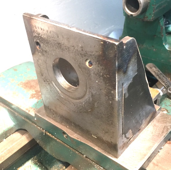
This is not some new discovery. It is just my version of a milling adapter for my lathe. The design has evolved over many years. Typically, whenever I need to use it, I make modifications to improve it. I always forget to take photos when making things. Recently it was used and I remembered to take photos while removing it from the lathe.
It is very simple. Remove the compound slide, Attach an angle plate. Mount the compound slide on the angle plate. Attach a vise to the slide.
Fig 01
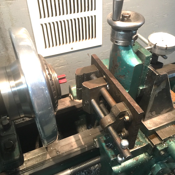
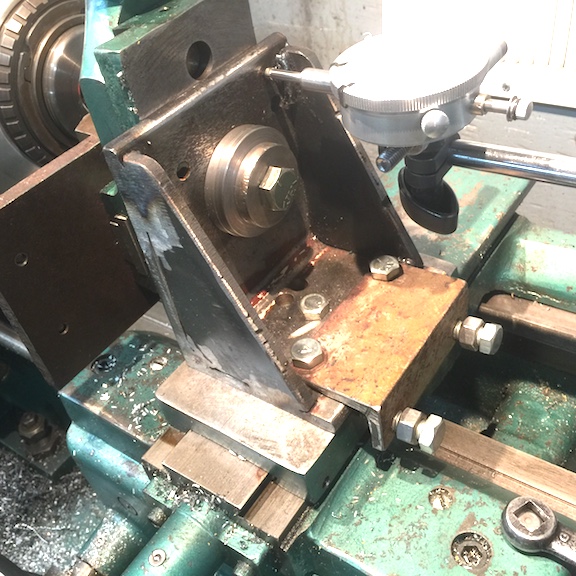
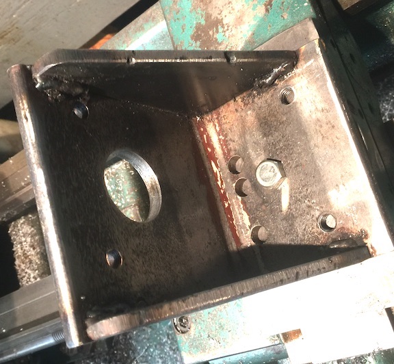
The compound slide is mounted to the angle plate with a bolt and spacers.
Fig 02
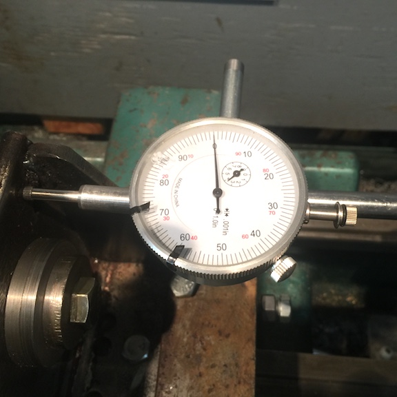
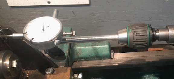
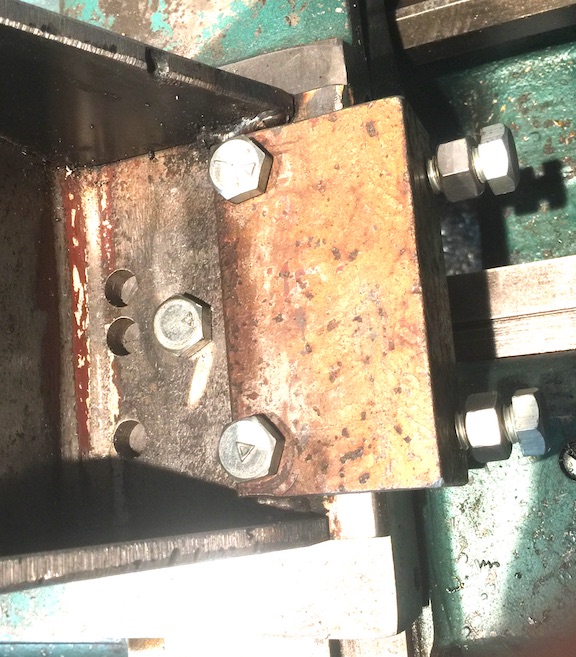
The carriage hand wheel is not graduated. A dial indicator touching the back side of the angle plate is used to measure carriage movement. The indicator is mounted in the tailstock drill chuck.
Fig 03, 04
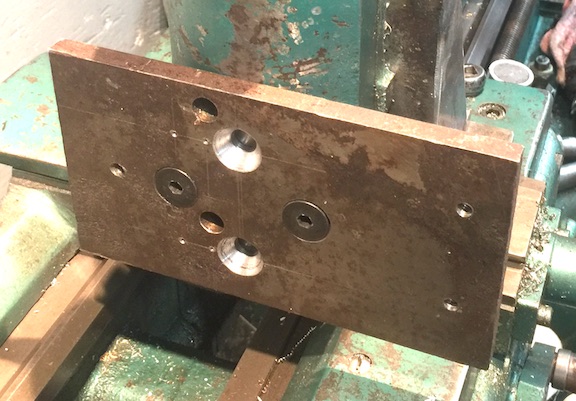
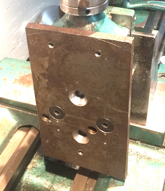
My drill press vise is mounted on a 1/2 steel plate for ease of clamping to the table. That plate was drilled to bolt into the T-nut groove on the slide. It can be mounted either horizontal or vertical. Originally, it was attached using hex bolts. The bolt heads interfered with the movement of the vise jaw. The most recent modification was to counter sink the vise plate to accept flat socket head bolts.
Figs 05, 06
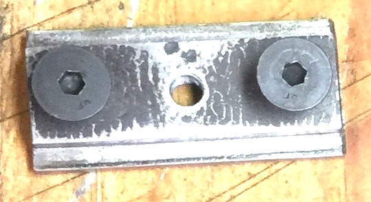
Initially a piece of 1/4 thick bar stock was used in place of a proper T-nut. The threads in that thin material did not seem adequate. The 1/2 thick T-nut below is the first part made with the mill adapter.
Fig 07
The angle plate is simply a piece of angle iron bored to accept the mounting boss from the compound slide. Reinforcements are welded on each side. It is attached to the cross slide with a single bolt
Fig 08, 09
The singe bolt is not adequate to keep the angle plate from rotating. It was necessary to make an adjuster to assist when properly aligning the angle plate to the spindle axis. The adjuster also prevents rotation after the set up is complete.
Fig 10
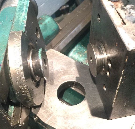
The boss on the compound slide was copied and bolted to the angle plate. The boss on the slide is longer than the thickness of the angle plate, this requires the use of a spacer to tighten against the plate.
Fig 11
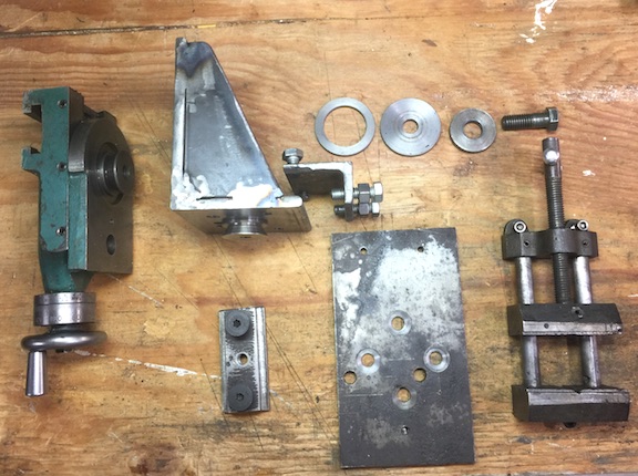
The individual parts are shown here. None of the parts are complex. For small light duty milling jobs, anyone should be able to create an adapter for their lathe. I have not provided any dimensions as very few people will have the same lathe of the same materials laying around to use.
Fig 12
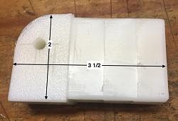
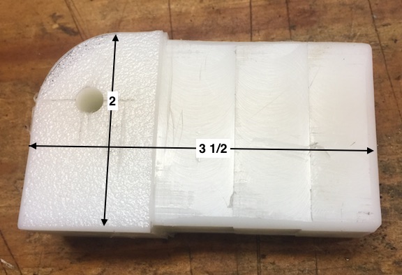
The most recent part is just a piece of high density polyethylene to fit another tool I have been working on. It was necessary to cut 0.062 from each of the 4 sides to make a tight fit into a piece of rectangular steel tubing. I considered using a router, but thought milling would be a better option. The router bit was held in a collet chuck. If you notice the lines in the milled surface are about 0.004 steps where the part was set over for each pass. This is the first time I have milled a surface that required more than one pass. For now it works.
Fig 13


 Reply With Quote

Bookmarks