Free 186 More Best Homemade Tools eBook:  
New: 300+ fresh build posts/day from 275 forums → BuildThreads.com

User Tag List

Page 1 of 2 1 2 LastLast
Results 1 to 10 of 17

Thread: 3Hp hydraulic power unit

Hybrid View

  1. #1
    Supporting Member Frank S's Avatar
    Join Date
    Aug 2015
    Location
    Peacock TX
    Posts
    12,617
    Thanks
    2,677
    Thanked 11,107 Times in 5,389 Posts

    Frank S's Tools

    3Hp hydraulic power unit

    Actually this would fall under the sub forum tools in progress but I think that one is gone.
    After building my plate roller rather than press it straight into service I decided that I wanted to power it hydraulically.
    This meant that I either had to dig through 10 tons of stuff still stashed away in 1 of my storage trailers to try and find where I had put my power unit or build another.
    To build another was the easier choice First I started with an old automotive lift power unit off of a larger lift actually it was one I had removed from an elevator I built 20 years ago when the coupling went bad a few years back.
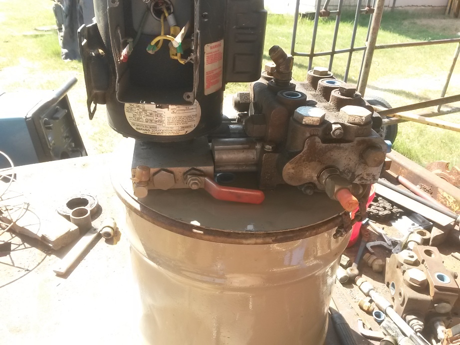
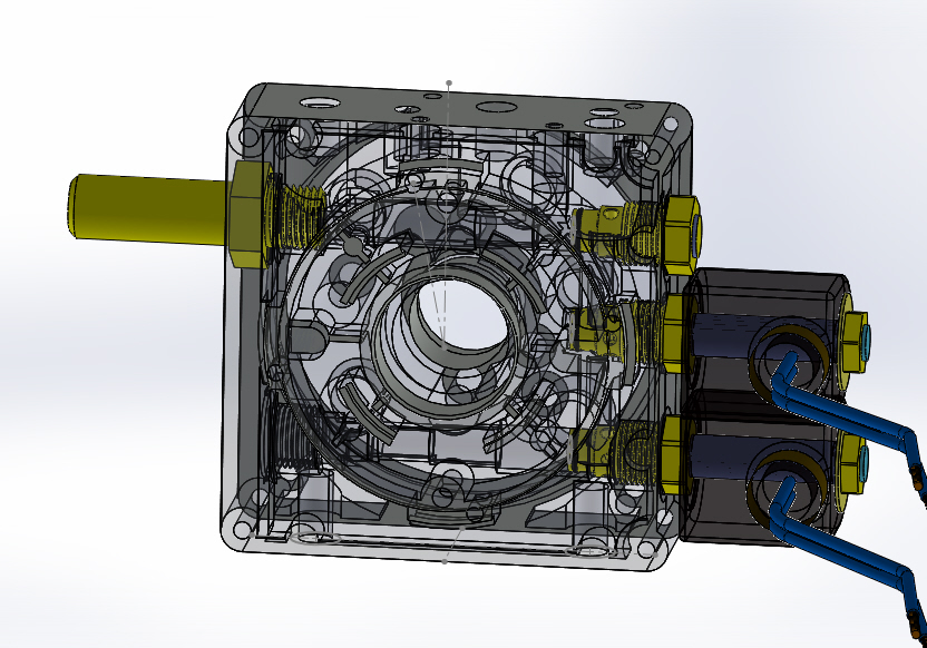
    I made a new pump to motor coupling "see Pump/ motor shaft coupling
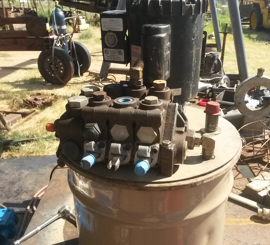
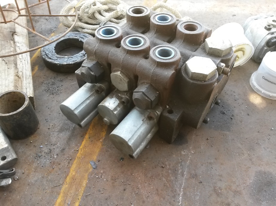
    Then I inspected several pumps that I had and checked the motor, then located a 4 way valve the one I decided to use is a 3 bank valve I will cap 2 of the sections for now but may need them when I use this power unit to test other equipment.
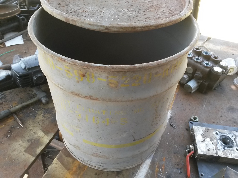
    next was to decide on a tank the 6 gallon plastic tank didn't fit my design criteria, so I settled on a 15 gallon steel drum it has a good diameter to height ratio being almost the same in height as in diameter.
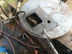
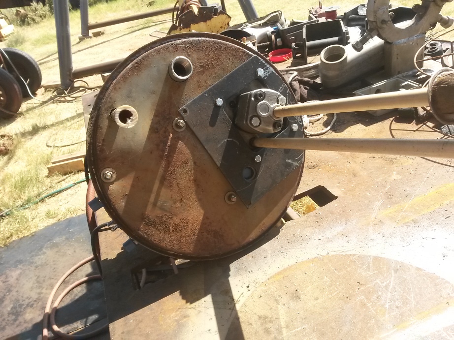
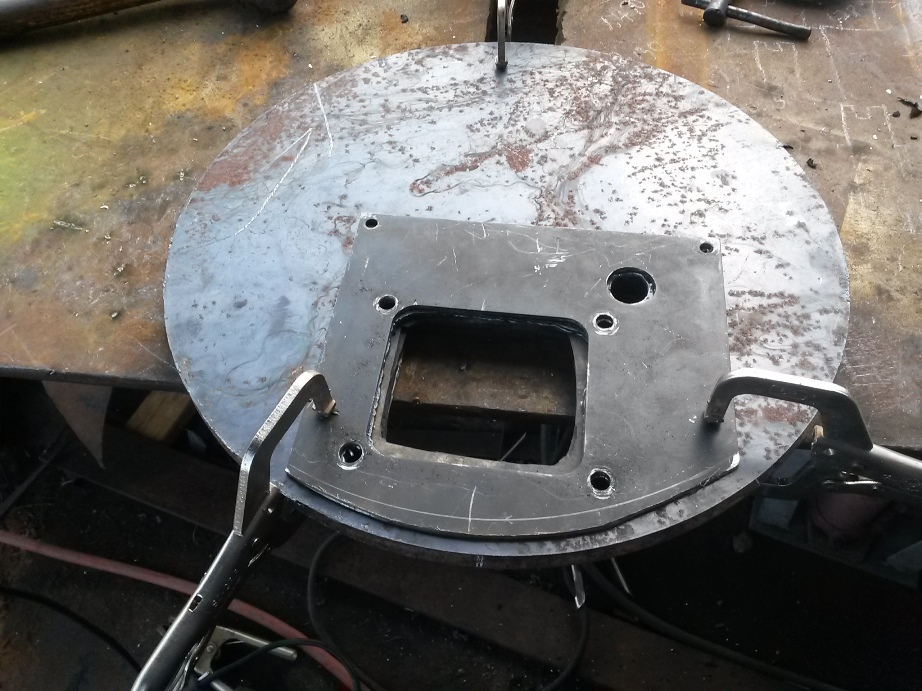
    I couldn't just mount the pump and motor directly to the top as the metal was too thin for my liking so I cut 3 old truck mud flaps to fill the depression in the top Then I needed to cut a round plate to cover these with and bolt through everything.
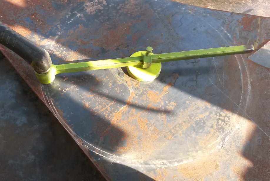
    this was why I made the Simple plasma torch circle guide to cut out the round piece
    here are some assembly pictures I still need to make up 3 hoses tomorrow if I have the correct fittings then will have to wait until I need to make a trip to town to get the oil.
    3Hp hydraulic power unit-20190819_163019az.jpg

    3Hp hydraulic power unit-20190819_163009az.jpg

    3Hp hydraulic power unit-20190819_162517az.jpg

    3Hp hydraulic power unit-20190811_115519az.jpg

    3Hp hydraulic power unit-20190811_115522az.jpg

    3Hp hydraulic power unit-20190818_180714sa.jpg

    3Hp hydraulic power unit-20190818_184040az.jpg

    3Hp hydraulic power unit-20190818_184728az.jpg
    Never try to tell me it can't be done
    When I have to paint I use KBS products

  2. The Following 13 Users Say Thank You to Frank S For This Useful Post:

    Andyt (Aug 21, 2019), baja (Aug 21, 2019), Christofix (Aug 20, 2019), clydeman (Jan 10, 2023), Crusty (Aug 20, 2019), HandymanNSons (Aug 26, 2019), Jon (Aug 22, 2019), KustomsbyKent (Aug 20, 2019), Little Rabbit (Aug 8, 2022), mwmkravchenko (Jun 22, 2024), NortonDommi (Aug 27, 2019), Scotty12 (Aug 20, 2019), Seedtick (Aug 20, 2019)

  3. #2
    Supporting Member Crusty's Avatar
    Join Date
    May 2019
    Location
    Dry Gulch, Tx
    Posts
    749
    Thanks
    220
    Thanked 926 Times in 345 Posts

    Crusty's Tools
    Your scrap pile(s) must be awesome Frank.
    If you can't make it precise make it adjustable.

  4. #3
    Supporting Member Frank S's Avatar
    Join Date
    Aug 2015
    Location
    Peacock TX
    Posts
    12,617
    Thanks
    2,677
    Thanked 11,107 Times in 5,389 Posts

    Frank S's Tools
    Quote Originally Posted by Crusty View Post
    Your scrap pile(s) must be awesome Frank.
    Better than average, but I need to start attending auctions again because much of the stuff is dwindling
    Never try to tell me it can't be done
    When I have to paint I use KBS products

  5. #4
    Supporting Member Frank S's Avatar
    Join Date
    Aug 2015
    Location
    Peacock TX
    Posts
    12,617
    Thanks
    2,677
    Thanked 11,107 Times in 5,389 Posts

    Frank S's Tools
    And here is 1 of my 10 pump power units
    This one was used to power 2 40 ton freight elevators from 1 to all 10 pumps could be used to raise either platform
    3Hp hydraulic power unit-10-pump-power-unit.jpg
    Never try to tell me it can't be done
    When I have to paint I use KBS products

  6. The Following User Says Thank You to Frank S For This Useful Post:

    MeJasonT (Aug 23, 2019)

  7. #5
    Supporting Member metric_taper's Avatar
    Join Date
    Mar 2017
    Location
    Marion, Iowa
    Posts
    760
    Thanks
    281
    Thanked 410 Times in 266 Posts

    metric_taper's Tools
    Quote Originally Posted by Frank S View Post
    And here is 1 of my 10 pump power units
    This one was used to power 2 40 ton freight elevators from 1 to all 10 pumps could be used to raise either platform
    Click image for larger version. 

Name:	10 pump power unit.jpg 
Views:	221 
Size:	167.4 KB 
ID:	30820
    I see some sort of manifold that must collect the outputs from each pump. I assume this has a check valve for each pump, so you can't back drive a pump that is off.
    What sequence method controls the various pumps? That has to be where the major cleverness is, assuming you designed that as well.
    I can't think of this being pressure, that just seems to have too many switches to adjust for cutin and cutout. A demand sensor of some type?
    I hope this is not some intellectual property that prevents you from sharing the operation.

  8. The Following User Says Thank You to metric_taper For This Useful Post:

    MeJasonT (Aug 26, 2019)

  9. #6
    Supporting Member Frank S's Avatar
    Join Date
    Aug 2015
    Location
    Peacock TX
    Posts
    12,617
    Thanks
    2,677
    Thanked 11,107 Times in 5,389 Posts

    Frank S's Tools
    Quote Originally Posted by metric_taper View Post
    I see some sort of manifold that must collect the outputs from each pump. I assume this has a check valve for each pump, so you can't back drive a pump that is off.
    What sequence method controls the various pumps? That has to be where the major cleverness is, assuming you designed that as well.
    I can't think of this being pressure, that just seems to have too many switches to adjust for cutin and cutout. A demand sensor of some type?
    I hope this is not some intellectual property that prevents you from sharing the operation.
    Well part of it might be considered intellectual property I can't show any actual pictures of the controller that I designed simply because I don't have access to them in a failed hard drive LOL I will tell you a little about it though but first
    your inquiry of the check valves and the distribution manifolds
    in each pump assembly I designed additional ports and cavity passages into an existing factory mono block motor/ pump adapter block then traveled to the manufacture in Italy a company by the name of Hydronit through a collaboration between their engineers and me we came up with a block that not only suited my needs but extended the usefulness of their products to be used in a wider field of applications. Their blocks already had cavities for check valves relief valves and 2 way solenoid operated poppet valves what my proposal was to make the cavities in the blocks to accept 4 way poppet valves by doing this it opened up a range which would accept flow restrictor valves duel power outputs differential pressure outputs and many other things such as building a multiple pump arrangement.
    here is a jpeg of the block It would be most difficult for anyone to duplicate this block from this drawing alone since there are many passages and ports in the block
    And yes their block is patented not sure about the changes that I made to them but I should hope they did
    3Hp hydraulic power unit-hydronit-valve-body1.jpg
    Now for the controller basically since my freight elevators were mainly used for 2 to 4 stops the controller to accelerate and slow the platform amounted to a few limit switches and a friction wheel sequential rotary switch. a series of relays and solenoid valves already in the pumps
    the operator or person at the door would push the call button a pump would start the platform began to move then that pump would go to full volume the 2nd pump would start with the fluid being briefly diverted a valve would close this would show a brief acceleration the 2nd solenoid would allow that one to go to full volume and the process would be repeated until as many pumps that were dedicated to the unit would all be on line as the platform reached the level going up the pumps would sequentially fall off until full stop. for going down it was a little different as the same valves in the pumps were used but the flow returned through the flow restrictor valves the pumps were not running. there were velocity check valves which would lock down the whole thing in the event of a broken hose. these were located in those manifolds you mentioned this was done to allow the platform to still be raised or lowered even if you removed a hose leading from 1 or more of the pumps, with a main velocity check made into the cylinders in the event of the hose to the cylinder was to burst or was cut intentionally. This did happen once by a guy who thought he could destroy the left by hacking a hose off with an ax. all he managed to do was get oil all over himself and a nice prison stay. `
    Never try to tell me it can't be done
    When I have to paint I use KBS products

  10. The Following User Says Thank You to Frank S For This Useful Post:

    MeJasonT (Aug 26, 2019)

  11. #7
    Supporting Member Crusty's Avatar
    Join Date
    May 2019
    Location
    Dry Gulch, Tx
    Posts
    749
    Thanks
    220
    Thanked 926 Times in 345 Posts

    Crusty's Tools
    I just scored a welding stool and a wide two drawer horizontal filing cabinet to hold my welding accessories by watching the Craigslist free section. Got some red steel and some stainless steel earlier in the year the same way. You gotta get there quick after it's posted and don't bother if it's out on the curb because it will be gone by the time you get there.
    If you can't make it precise make it adjustable.

  12. #8
    Supporting Member metric_taper's Avatar
    Join Date
    Mar 2017
    Location
    Marion, Iowa
    Posts
    760
    Thanks
    281
    Thanked 410 Times in 266 Posts

    metric_taper's Tools
    So what sort of hydraulic motor is on your plate roller? I assume that is what will be powered via this pump assembly. I'm not familiar with the pump your using, is that a spool valve manifold contraption, with a gear pump?

  13. #9
    Supporting Member Frank S's Avatar
    Join Date
    Aug 2015
    Location
    Peacock TX
    Posts
    12,617
    Thanks
    2,677
    Thanked 11,107 Times in 5,389 Posts

    Frank S's Tools
    Quote Originally Posted by metric_taper View Post
    So what sort of hydraulic motor is on your plate roller? I assume that is what will be powered via this pump assembly. I'm not familiar with the pump your using, is that a spool valve manifold contraption, with a gear pump?
    The pump is gear 0.6 cubic inch per revolution or 2.1 gal per minute at 2800 RPM the block between the pump and motor has an internal relief valve factory set at 4000 PSI
    The bank valve is a spool valve with relief sat to 3000 PSI by changing out a single plug it can be used as power beyond with other valves. I have several dozen 4 way poppet solenoid valves with 12 vdc coils but I didn't have a suitable body to mount some of them in and no good way to create a cavity cutter or a burnishing tool Ideally this would have been the preferred way to have built it as everything would have been more clean and compact. If I had the cavity cutters I could have made a mono block containing all passages and mounted the pump and motor directly to it. As it is this spool valve set up is way oversized but I'm not going to worry about it.
    the motor on the plate roll is a Parker wheel motor 2.5 cubic inches @ 2750 PSi it has 832 in.lb. torque @ 1 gallon per minute The minimum flow for it is 1/2 gallon per min. the max is 11 gallon per minute max torque @ max flow would be 838 in. lb but it would also be truning at 897 PRM
    The plate roll has a 10 to 1 speed reduction which should yield 693 ft. lbs of torque to the rolls except for the obvious losses due to internal leakage of the oversized spool valve plus other accumulated losses IE low flow rate through the motor the pump not being new and so forth I figure there could possibly be a 25 to 30% loss of efficiency if I wind up with 400 ft lbs I'll be more than happy. But I may find that the target main roll RPM of 5 will turn out to be much higher than that even with such a diminutive sized power unit if this is the case I will have to either feather the spool valve or add a flow restrictor or I could up the reduction by adding a second shaft and sprocket system if need be.
    I should find out in a couple of days when Bob pays me for mounting the APU on his truck.
    Never try to tell me it can't be done
    When I have to paint I use KBS products

  14. The Following User Says Thank You to Frank S For This Useful Post:

    metric_taper (Aug 21, 2019)

  15. #10
    Supporting Member MeJasonT's Avatar
    Join Date
    Jun 2016
    Location
    Lake District in UK
    Posts
    432
    Thanks
    456
    Thanked 312 Times in 176 Posts

    MeJasonT's Tools
    Frank,
    I have a pressure washer with the a 3 stage pump with a relief set for 4000 psi , I wonder if it would make a suitable hydraulic unit for me. simply swapping out the medium from water to hydraulic oil ?3Hp hydraulic power unit-71bios7p-9l._sl1500_.jpg
    Last edited by MeJasonT; Aug 21, 2019 at 01:56 AM.
    Citizen of the "New democratic" Republic of Britain, liberated from the EuroNation

Thread Information

Users Browsing this Thread

There are currently 1 users browsing this thread. (0 members and 1 guests)

Bookmarks

Posting Permissions

  • You may not post new threads
  • You may not post replies
  • You may not post attachments
  • You may not edit your posts
  •