Free 186 More Best Homemade Tools eBook:  
Get 2,000+ tool plans, full site access, and more.

User Tag List

Results 1 to 5 of 5

Thread: Attaching an occasional use encoder to a lathe spindle.

  1. #1
    Supporting Member tonyfoale's Avatar
    Join Date
    Nov 2016
    Location
    Spain
    Posts
    1,566
    Thanks
    690
    Thanked 2,648 Times in 709 Posts

    tonyfoale's Tools

    Cool Attaching an occasional use encoder to a lathe spindle.

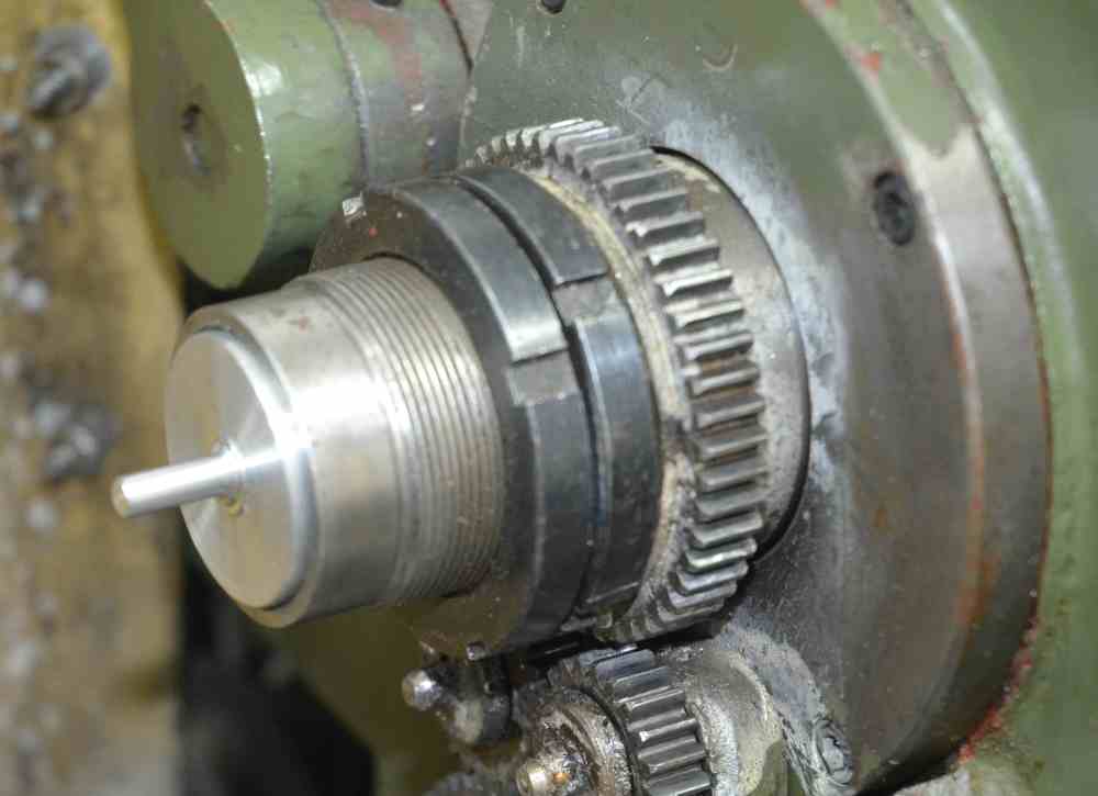
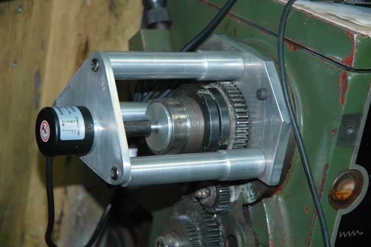
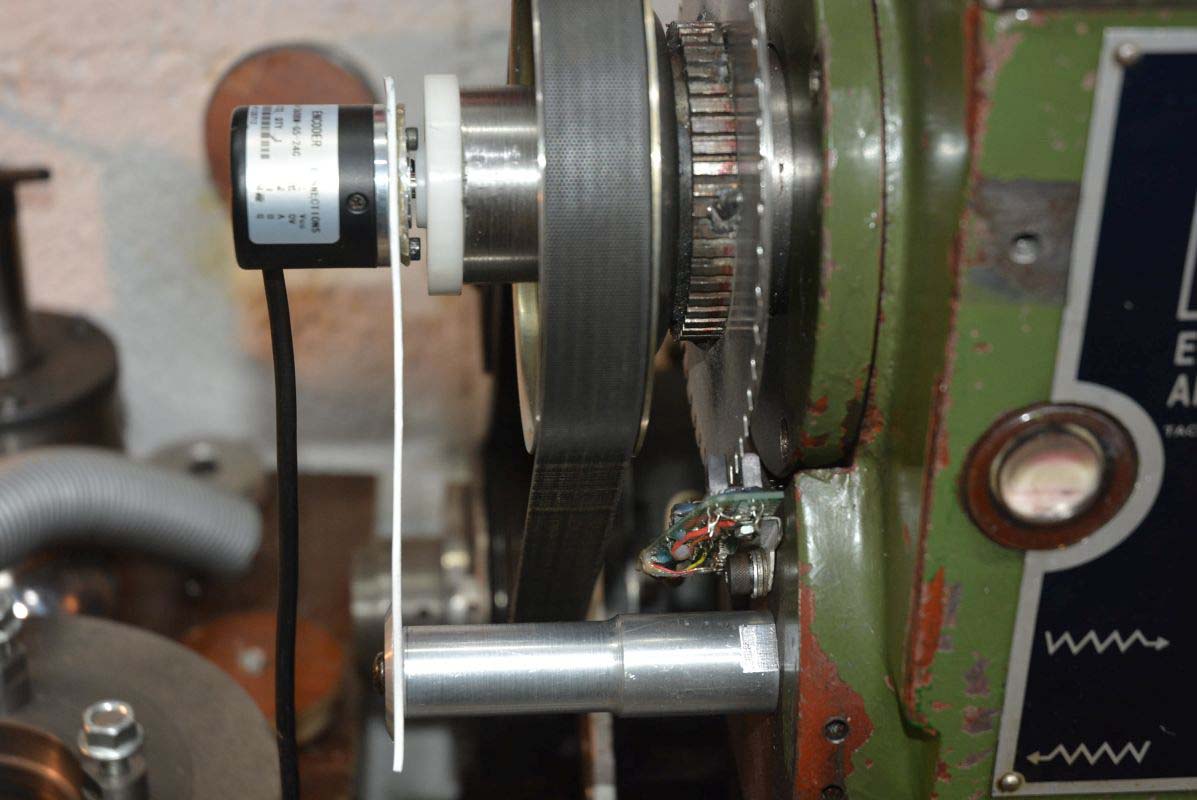
    There are times when I need to fit a rotary encoder to my lathe for precise measuring. Accurately measuring the profile of camshafts is one example use. I originally used a 3 post mount, but as you can see after the drive belt conversion (described in a previous post on this forum) and now a large 50 tooth timing wheel that is not possible. The solution, which was inspired by a friend, was to support the encoder with the spindle plug and then it is only necessary to prevent rotation. The torque is absolutely minimal so I used a piece of 2 mm plastic sheet which is rigid in the rotation direction but flexible in the axial direction, thus preventing any misalignment from loading the bearings in the encoder.
    It only takes 30 seconds to mount it when needed.

    Attaching an occasional use encoder to a lathe spindle.-cam-measuring-07.jpg Attaching an occasional use encoder to a lathe spindle.-rotary-encoder-01.jpg Click for full size images

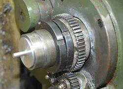
    This is my original encoder mount. A piece of rubber tube connected the pip on the spindle plug to the encoder shaft.

    Attaching an occasional use encoder to a lathe spindle.-encodermount001.jpg Attaching an occasional use encoder to a lathe spindle.-encodermount002.jpg

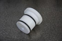
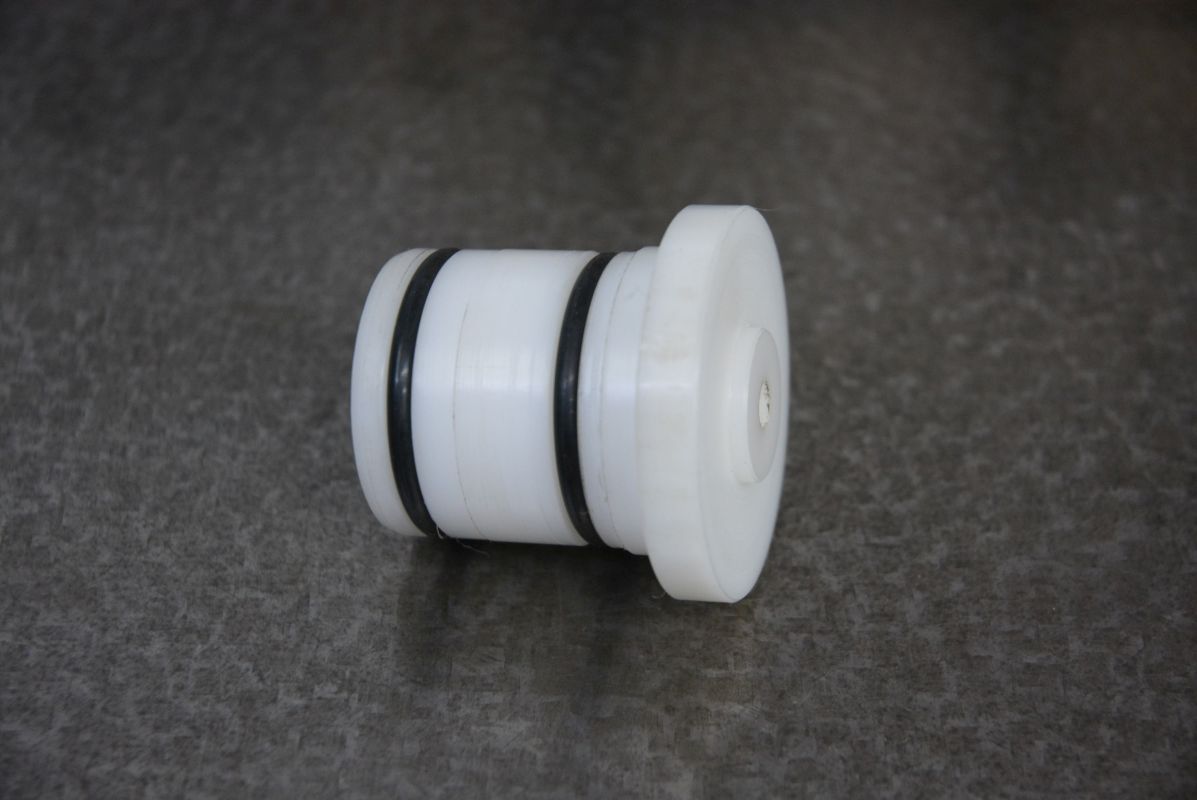
    Here is the new plug made in Delrin. The fit is so good that the O-rings are not necessary but seem like a good idea. All machining including the hole for the encoder spindle was done in a single setting to ensure concentricity. The encoder spindle is a push fit in the plug and no other fixation was needed.

    Attaching an occasional use encoder to a lathe spindle.-encodermount003.jpg Attaching an occasional use encoder to a lathe spindle.-encodermount004.jpg

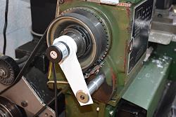
    Everything in place. The plastic sheet is wide and hence rigid in the direction to locate the rotary motion of the encoder, but thin and hence flexible in the axial direction which allows for misalignment tolerances.

    BTW. The eagle eyed may have noticed that there is oil in the sight glass on the old photo but there is no oil in today's photos. A while back I changed from oil to grease for bearing lubrication. The bearings run much cooler now, due to the lack of oil churning.

    186 More Best Homemade Tools eBook

  2. The Following 6 Users Say Thank You to tonyfoale For This Useful Post:

    emu roo (Nov 16, 2022), Home-PC (Nov 16, 2022), Jon (Nov 16, 2022), mwmkravchenko (Nov 16, 2022), nova_robotics (Nov 16, 2022), rebuilder1954 (Nov 17, 2022)

  3. #2
    Supporting Member metric_taper's Avatar
    Join Date
    Mar 2017
    Location
    Marion, Iowa
    Posts
    586
    Thanks
    228
    Thanked 257 Times in 153 Posts

    metric_taper's Tools
    Tony, I have a 1976 Jet 1024 lathe. It was made in Taiwan. The head stock is similar casting as well the sight glass is the same. I found when I pulled the spindle many years back, that there was only a single hole going from the oil reservoir to the bearing (the hole level with the normal oil level). The sight glass is a front plug for this reservoir. This hole was straight back to the roller bearing. So the sight glass could show oil at the lower line level, but the bearing could be dry. So I modified both the front and rear bearing reservoirs, by drilling a 1/8" hole from the rear bottom of that reservoir to the bottom of where the bearing cup is. So now when I run the lathe, the oil is pumped out of the reservoir and circulates with the bearing (which was unintended). When running the sight glass shows the level has dropped to nothing on the sight glass. Your lathe probably did not have the design or manufacturing error, so the bearings were working as an oil pump.

    I know you reworked your whole spindle arrangement on this lathe, and did away with the back gear. I think you filled the head stock with concrete to increase mass and reduce vibrations.

    In your last two photos of this post, you do have a photo-optic shaft encoder. Is this added one more resolution?

    2000 Tool Plans

  4. #3
    Content Editor
    Supporting Member
    DIYer's Avatar
    Join Date
    Aug 2013
    Posts
    3,056
    Thanks
    773
    Thanked 1,852 Times in 1,653 Posts


    Thanks tonyfoale! We've added your Rotary Encoder Mount to our Lathe Accessories category,
    as well as to your builder page: tonyfoale's Homemade Tools. Your receipt:


  5. #4
    Supporting Member tonyfoale's Avatar
    Join Date
    Nov 2016
    Location
    Spain
    Posts
    1,566
    Thanks
    690
    Thanked 2,648 Times in 709 Posts

    tonyfoale's Tools
    Quote Originally Posted by metric_taper View Post
    Tony, I have a 1976 Jet 1024 lathe. It was made in Taiwan. The head stock is similar casting as well the sight glass is the same. I found when I pulled the spindle many years back, that there was only a single hole going from the oil reservoir to the bearing (the hole level with the normal oil level). The sight glass is a front plug for this reservoir. This hole was straight back to the roller bearing. So the sight glass could show oil at the lower line level, but the bearing could be dry. So I modified both the front and rear bearing reservoirs, by drilling a 1/8" hole from the rear bottom of that reservoir to the bottom of where the bearing cup is. So now when I run the lathe, the oil is pumped out of the reservoir and circulates with the bearing (which was unintended). When running the sight glass shows the level has dropped to nothing on the sight glass. Your lathe probably did not have the design or manufacturing error, so the bearings were working as an oil pump.
    Yes, a totally crazy and incompetent design. I also drilled a hole as you describe, some years before I changed to grease. I think that we have both made posts about this in the past.

    Quote Originally Posted by metric_taper View Post
    In your last two photos of this post, you do have a photo-optic shaft encoder. Is this added one more resolution?
    This is for screw cutting with my electronic conversion. That 50 tooth wheel was only made and fitted about a week ago. Originally when I did the electronic conversion I used the single pulse/revolution RPM signal to drive a velocity based screw cutting method. The Mach3 CNC software uses the same method. Basically, you measure the spindle speed and set the carriage speed to set the thread pitch. The concept is flawed because it is incapable of following spindle speed variations within a single revolution. In practice this was not a problem for my lathe, it has a 5hp motor and a heavy chuck, the inertia of which reduced speed variation during a revolution, but you still have the effects of pulley eccentricity etc. A smaller lathe would not be so accommodating.

    Although the single pulse worked well enough I just did not like it and a while back I added a 10 pulse wheel for speed sensing but kept the original single pulse wheel for indexing. So that updated the spindle velocity 10 times/revolution. To be honest I did not notice any difference in the thread quality, but I felt happier. However, the screwcutting algorithms were still velocity based, whereas a thread is a position based concept, a pitch based on a rotation. Real CNC machines use position based algorithms which need rotary encoders of fine resolution. I did consider fitting a rotary encoder but to keep the spindle hole clear it would have had to be belt driven which I did not want.

    I thought that a 100 tooth wheel might be enough to produce good threads using a position based algorithm. Without any carriage inertia, general structural flex and carriage motor delay that would mean that every single pitch would theoretically be made up of 100 steps of 0.01 mm for a 1mm pitch thread. We do have inertia and other smoothing influences so the actual results would be better and I designed some software velocity based smoothing which I thought would make it close to perfect. It was a simple software change to test the effectiveness of the software smoothing with the 10 pulse wheel. It worked well but further reflection led me to consider that a 50 tooth wheel would be better than 100 and that is what you see in the photos. It was fitted a few days back and I feel happier knowing that I have a position based system with velocity smoothing, even though the thread quality seems the same as the single pulse velocity based system. For a low inertia mini-lathe this is a much better system than the single pulse Mach3 style solution.

    Attaching an occasional use encoder to a lathe spindle.-10teeth-02.jpg Attaching an occasional use encoder to a lathe spindle.-ballscrew_084.jpg Click images for full size pix.
    This was the previous 10 tooth wheel on the left. The single index pulse sensor is mounted inside the head. The multi-tooth wheels would have been also but it means pulling the spindle to do that. hence the external fitting.

  6. #5

Thread Information

Users Browsing this Thread

There are currently 1 users browsing this thread. (0 members and 1 guests)

Tags for this Thread

Bookmarks

Posting Permissions

  • You may not post new threads
  • You may not post replies
  • You may not post attachments
  • You may not edit your posts
  •