
 LinkBack URL
 About LinkBacks


Yes, a totally crazy and incompetent design. I also drilled a hole as you describe, some years before I changed to grease. I think that we have both made posts about this in the past.Originally Posted by metric_taper

This is for screw cutting with my electronic conversion. That 50 tooth wheel was only made and fitted about a week ago. Originally when I did the electronic conversion I used the single pulse/revolution RPM signal to drive a velocity based screw cutting method. The Mach3 CNC software uses the same method. Basically, you measure the spindle speed and set the carriage speed to set the thread pitch. The concept is flawed because it is incapable of following spindle speed variations within a single revolution. In practice this was not a problem for my lathe, it has a 5hp motor and a heavy chuck, the inertia of which reduced speed variation during a revolution, but you still have the effects of pulley eccentricity etc. A smaller lathe would not be so accommodating.
Although the single pulse worked well enough I just did not like it and a while back I added a 10 pulse wheel for speed sensing but kept the original single pulse wheel for indexing. So that updated the spindle velocity 10 times/revolution. To be honest I did not notice any difference in the thread quality, but I felt happier. However, the screwcutting algorithms were still velocity based, whereas a thread is a position based concept, a pitch based on a rotation. Real CNC machines use position based algorithms which need rotary encoders of fine resolution. I did consider fitting a rotary encoder but to keep the spindle hole clear it would have had to be belt driven which I did not want.
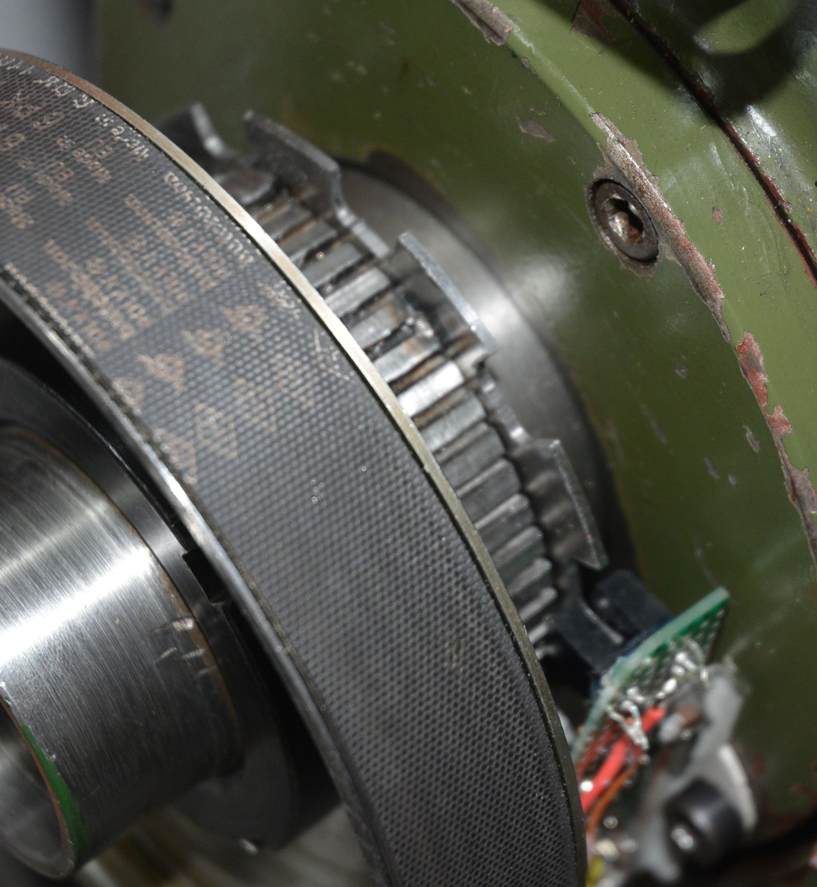
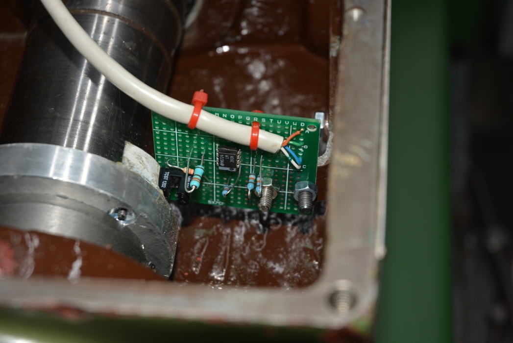
I thought that a 100 tooth wheel might be enough to produce good threads using a position based algorithm. Without any carriage inertia, general structural flex and carriage motor delay that would mean that every single pitch would theoretically be made up of 100 steps of 0.01 mm for a 1mm pitch thread. We do have inertia and other smoothing influences so the actual results would be better and I designed some software velocity based smoothing which I thought would make it close to perfect. It was a simple software change to test the effectiveness of the software smoothing with the 10 pulse wheel. It worked well but further reflection led me to consider that a 50 tooth wheel would be better than 100 and that is what you see in the photos. It was fitted a few days back and I feel happier knowing that I have a position based system with velocity smoothing, even though the thread quality seems the same as the single pulse velocity based system. For a low inertia mini-lathe this is a much better system than the single pulse Mach3 style solution.
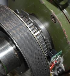
Click images for full size pix.
This was the previous 10 tooth wheel on the left. The single index pulse sensor is mounted inside the head. The multi-tooth wheels would have been also but it means pulling the spindle to do that. hence the external fitting.

 Reply With Quote

Bookmarks