
 LinkBack URL
 About LinkBacks


I need to fit a new ring gear on a flywheel. I want to know
the sizes of the ring gear and the flywheel to get an idea how
hot to get the ring to slip it into the flywheel.
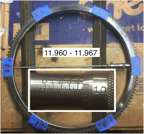
I have my dads Starrett 0-12 inside micrometer set to measure the ID
of the gear. Those measurements vary between 11.960 and 11.967.
Twelve measurements at 6 positions averaged to 11.9615.
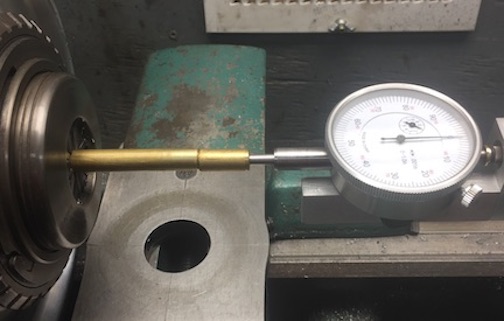
I have nothing to accurately measure the OD of the12 flywheel.
After some thought, the lathe could used as a caliper. A brass rod
was freshly faced in the chuck and a dial indicator mounted in the
tailstock chuck. For my purposes the actual size is not as critical
as the difference in size.
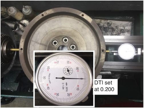
DTI Tail Stock Chuck Adapter
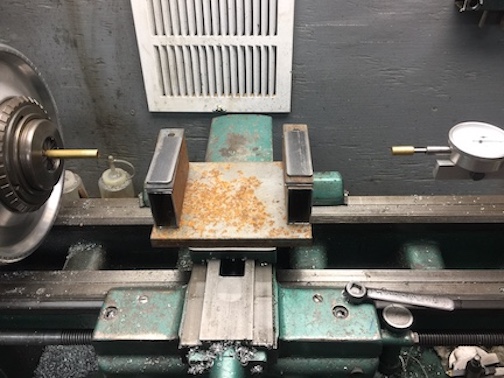
By removing the compound slide and stacking shims on the
cross slide, the flywheel can rest firmly at proper height to
contact the rod and the indicator. The cross slide easily moves
the flywheel to center with the indicator.
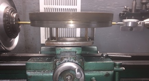
With the flywheel in place, the tailstock quill was advanced and
locked with the indicator reading 0.200. Then back the cross
slide out, rotate the flywheel 60˚ and slide it back into place.
The clutch bolt holes provided reference for rotating the wheel.
Working all the way around, 6 measurements were within 0.001
off some unknown value.
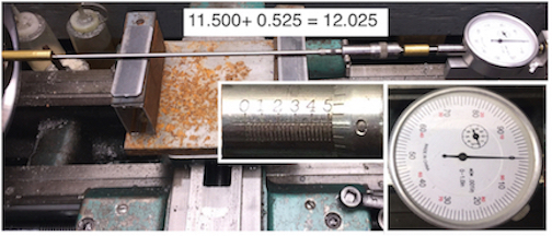
Removed the flywheel and replaced with the inside micrometer.
Then adjust the micrometer so the DTI reads 0.200.
The flywheel measures 12.025
12.025 - 11.960 = 0.065
According to an online calculator,
https://goodcalculators.com/thermal-...on-calculator/
the steel ring gear will expand about 0.0657I.D. at ∆T of 750˚f.
The service manual says to heat the gear to 400˚f, and to not
exceed 450˚f. This makes sense to me as the gear is heat treated.
This is WAY too hot to avoid ruining the temper in this gear.
Finding these measurements made me to do more research. I have discovered several sources with a gear, same fitment description, with the advertised size of 11.994.
12.025 - 11.994 = 0.031
∆T of 425˚ is 0.037 should expand the gear to 12.031.
It should slip right on.
Will let you know when the new gear arrives.


 Reply With Quote

Bookmarks