
 LinkBack URL
 About LinkBacks


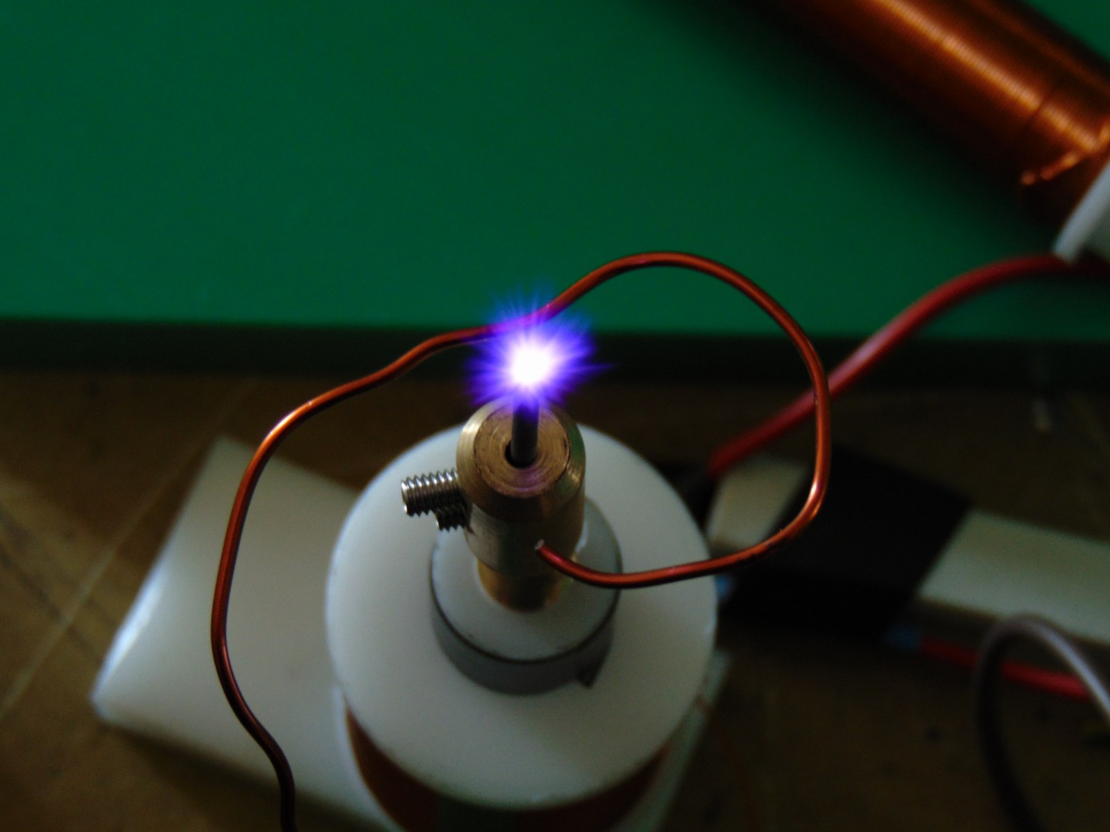
Thanks Stefano. You are on another plane of knowledge from me with electronics. I'm sure the Wiz will be along soon and understand all. Interesting that the Quartz/Pyrex and horn are part of a means to keep ozone down. Like to boost the efficiency? Or as a catalyst?
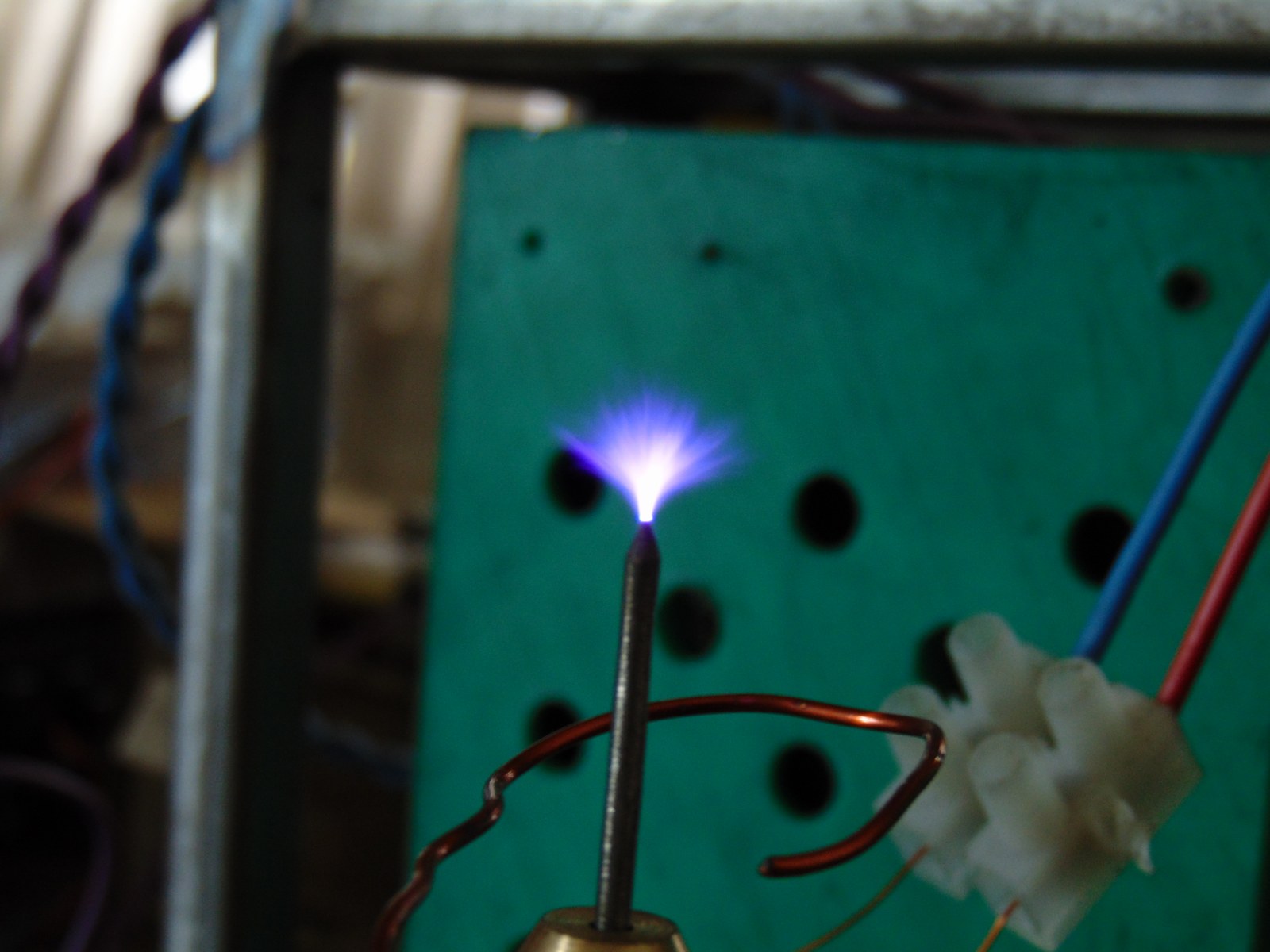
I was hoping that you were not going for such a huge flame as it seems dangerous if nothing else that much heat in a horn would sure mess up your nice polish job in a hurrya big tube amp already puts out a lot of heat, having two plasma torches going on would be hell during the summer! Also you are going for a single flame, not double like in the vid PJ's/ Wiz posted.
Interesting my old Heil's operate at the exact same frequency you are wanting the plasma for. I salute you for your diligence. Thanks for the update and stay safe.


 Reply With Quote


 Usually I find that letting it go for a day or two, something bubbles to the surface that either puts me on the right track or the actual solution. Allow some Ω time. ~¿@


 by rendoman - Hi!
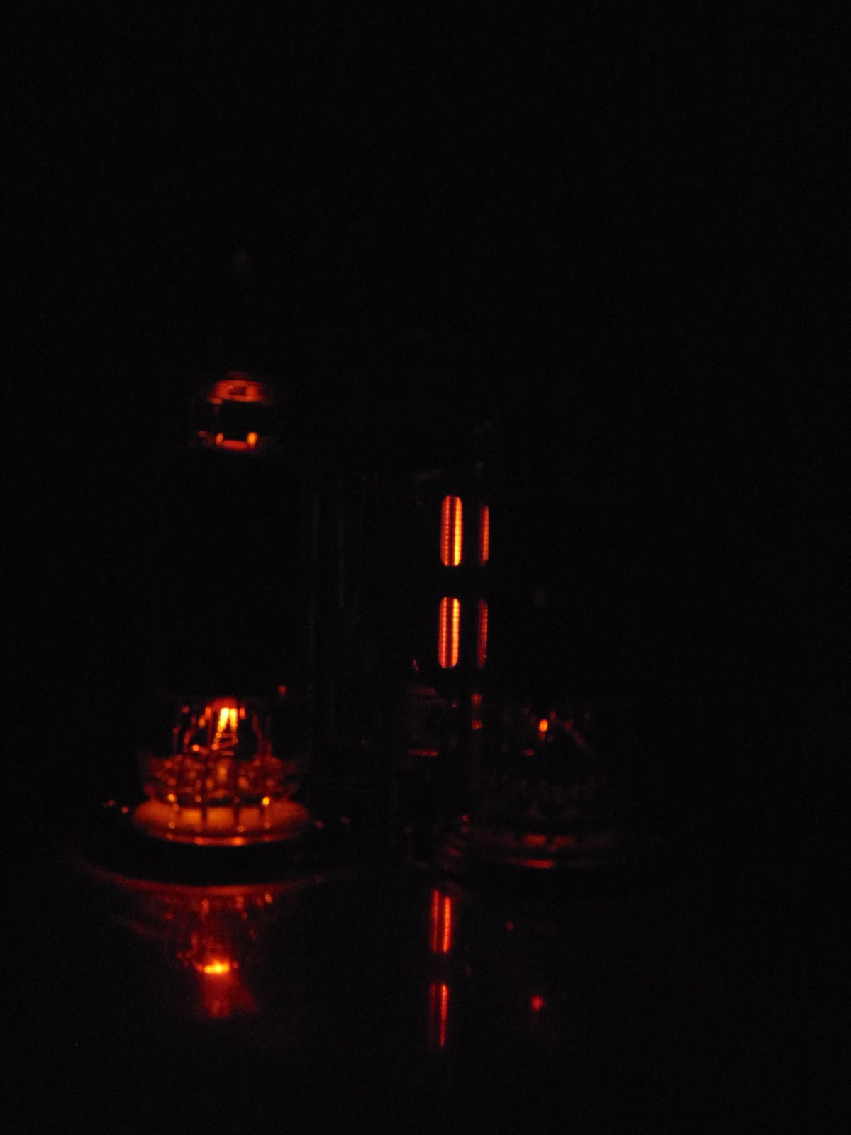
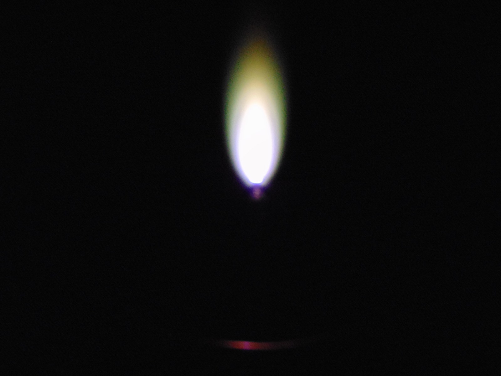
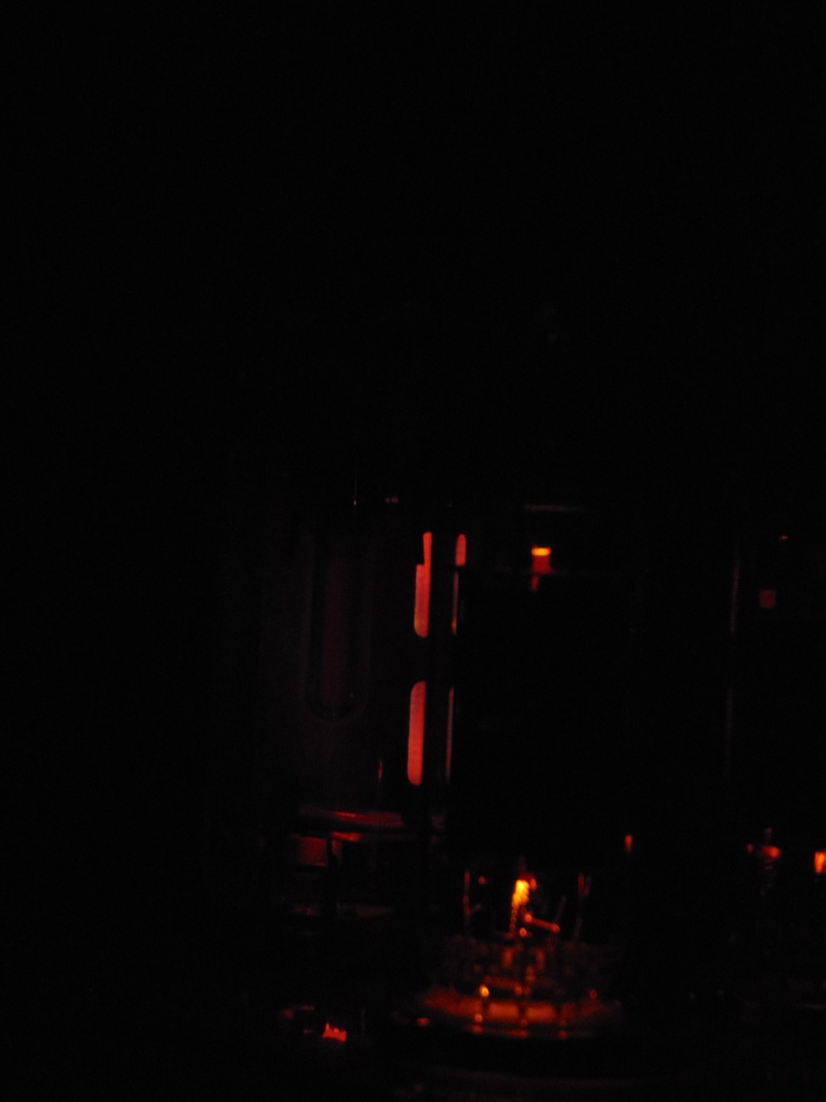
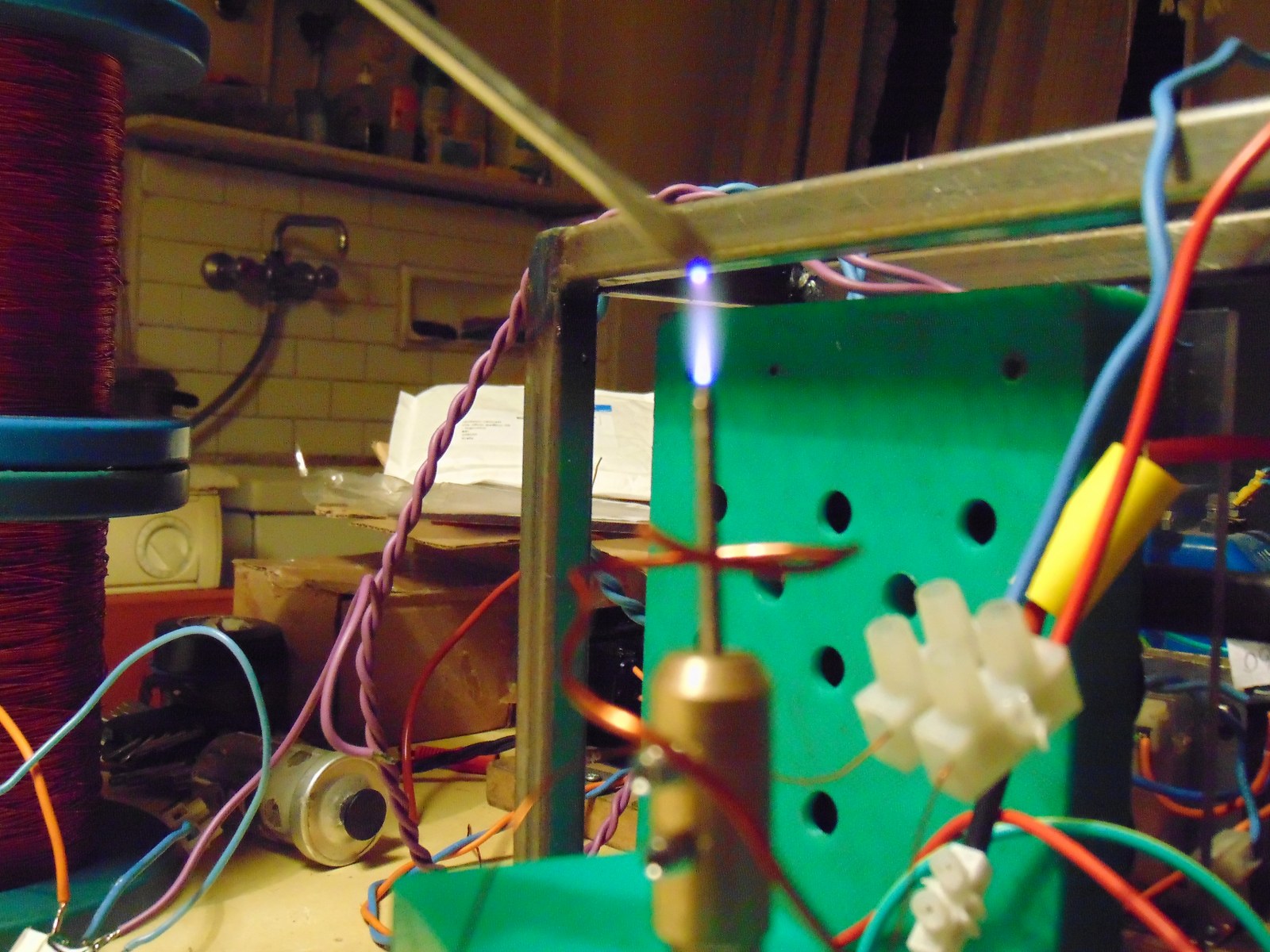
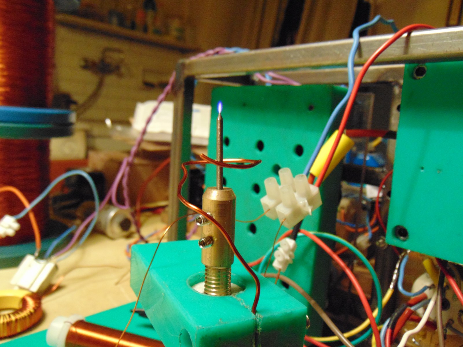
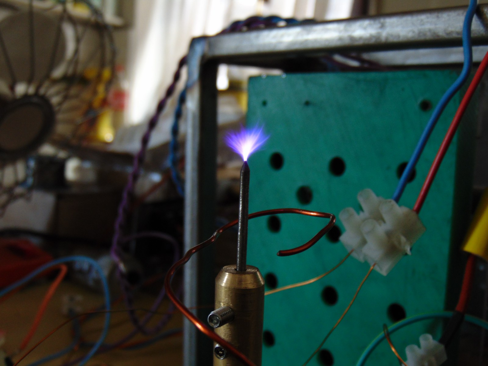
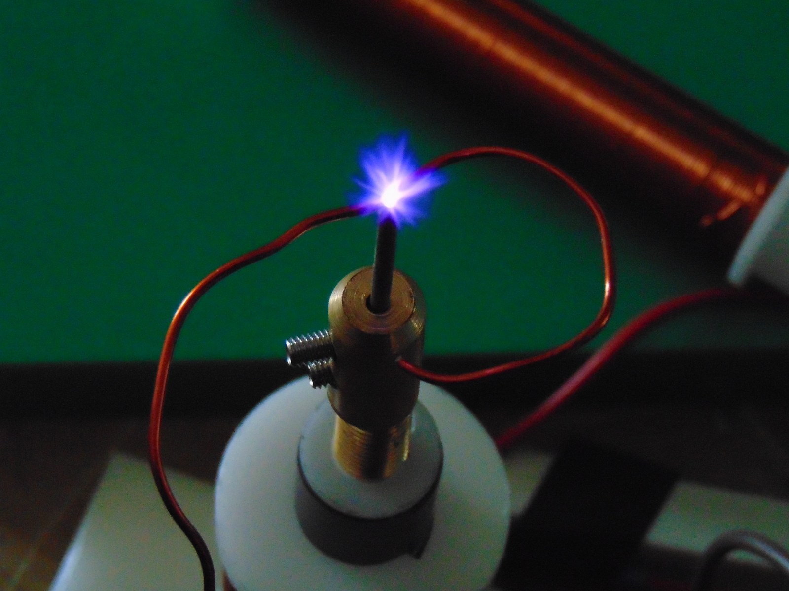
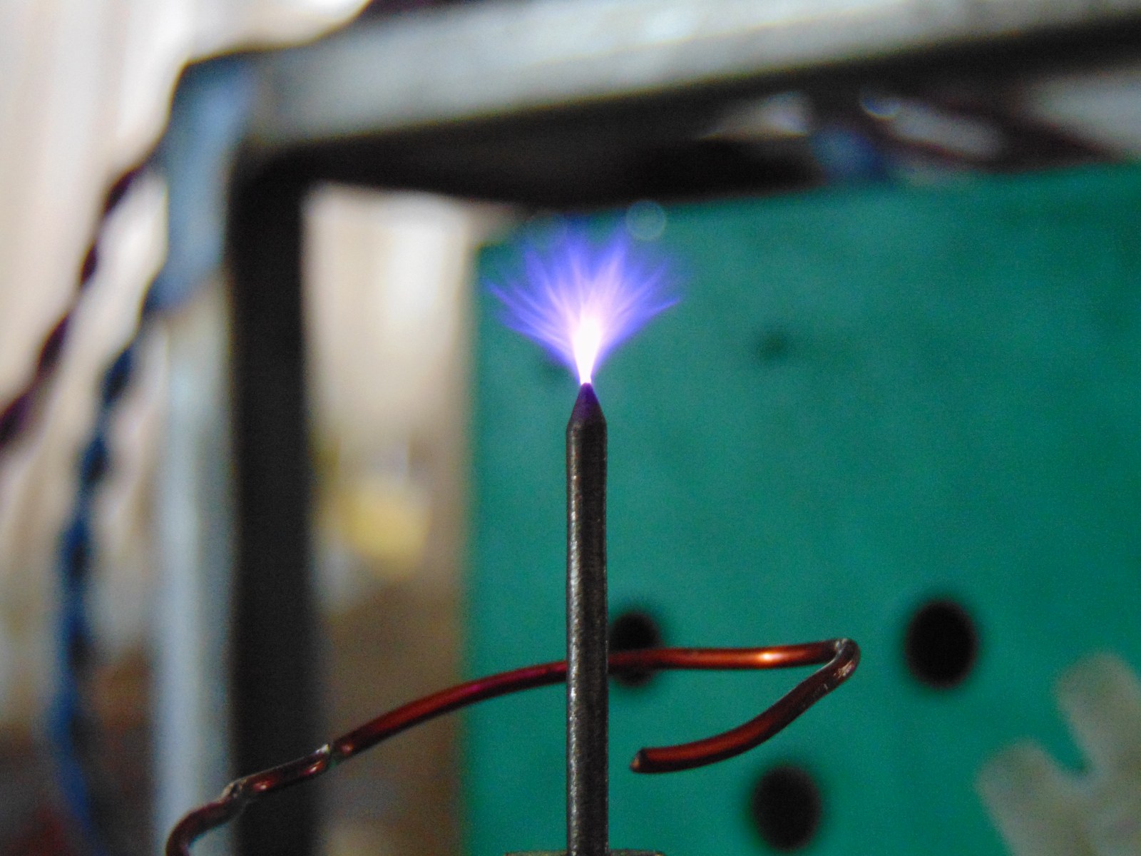
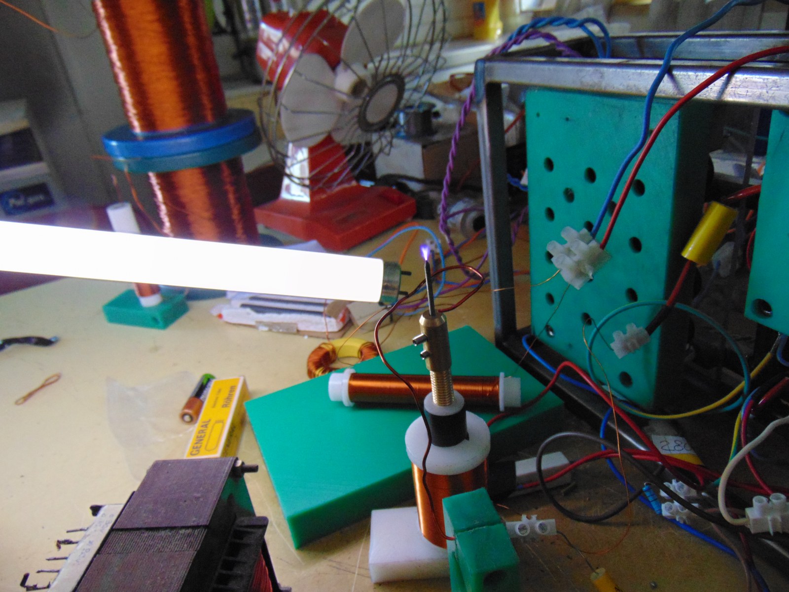
This evening I tried some experiments with audio, for sure strange things happened! Got huge troubles with some audio tube connection, maybe due to oxidation of pcl82 socket, then terrible Gnd hum and buzz from flame. I tried different things, the big problem was m6 inox allen plus nut close to reaction ring, it's a couple of week that I see strange behavior of that component. I remove the part and the flame starts oscillating "Pin It")


Bookmarks