
 LinkBack URL
 About LinkBacks


Drum brakes are a thing of the past arent they? So why would I want to make a grinder for motorcycle drum brakes when disc brakes are so much better? Well, I race motorcycles in classic races. That means old farts wobbling about on old motorcycles. Classic racing organisations have eligibility rules constraining the bikes to use features from way back. Each organisation has its own rules, but the ones that I race with ban disc brakes in the categories that interest me. So instead of using nice efficient disc brakes I have to try and squeeze the maximum performance from drum brakes.
With use drums become distorted and also the rubbing surface can become very hard and shiny. This is not good for optimum braking and it requires a lot of cutting force if you try to machine it with a single point lathe tool. Hence it is better to grind which can dramatically reduce the cutting forces and strain on the tool used.

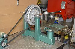
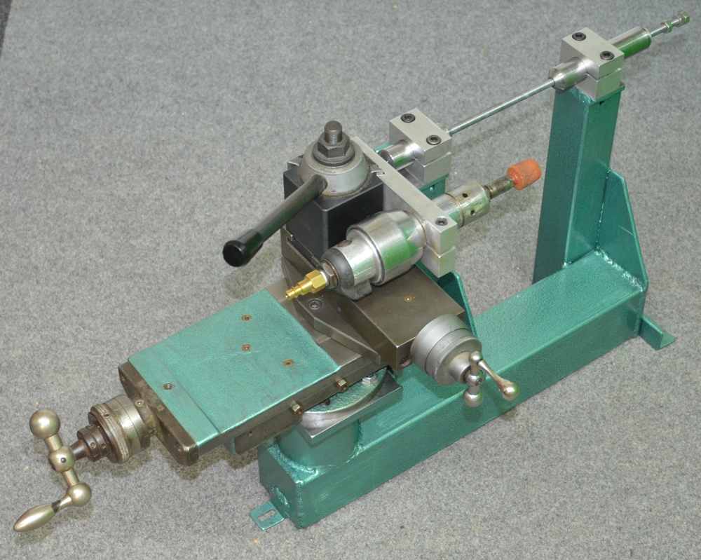
Here are a couple of pix. of the device that I made. Although I always grind drums using a complete wheel these photos are without a rim. It is only necessary to move the drive motor closer to enable the belt to fit onto the rim rather than the hub.
Spoking a rim onto a drum brake hub causes addition distortion to the surface of the drum and so any truing of the drum should be done with the wheel complete and not just the hub.
Many hubs are difficult shapes to mount in a lathe accuratelyeven if you have one large enough for the whole wheel, and in any case to ensure accuracy it is better to rotate the wheel about it own bearings to ensure true concentricity of the drum.
I have a lathe just large enough for a wheel and an internal tool post grinder, however I decided that it would be better to build a tool dedicated to just grinding drums.
Here are a couple of pix. of the device that I made. Although I always grind drums using a complete wheel these photos are without a rim. It is only necessary to move the drive motor closer to enable the belt to fit onto the rim rather than the hub.
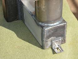
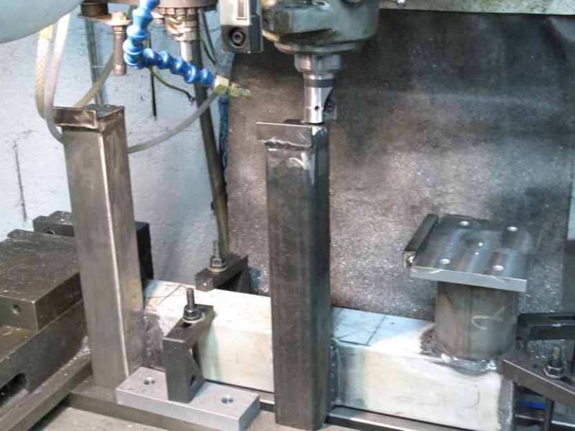
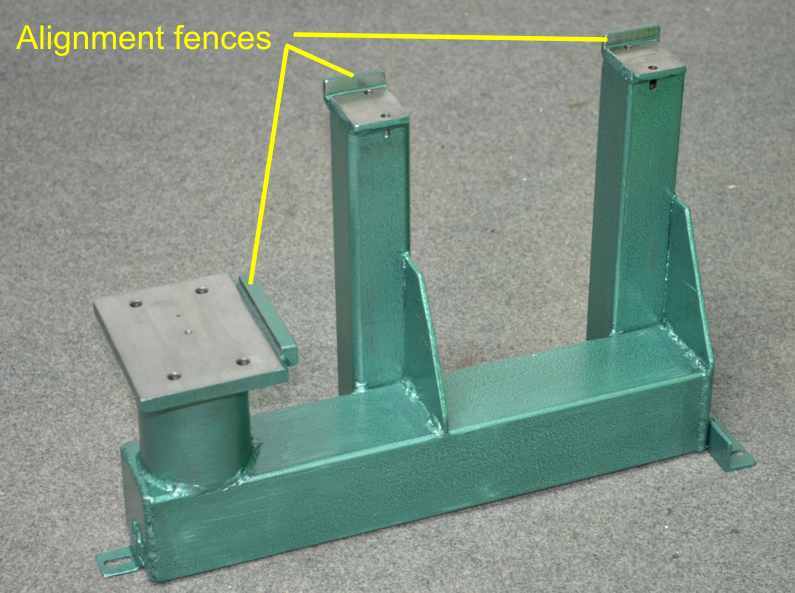
I made a frame out of materials from the scrap box. I used a stick welder to glue the frame together and machined the assembly in a milling machine to ensure good alignment of all surfaces.
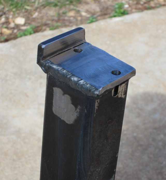
I also added some fences machined at right angles to ensure good alignment.

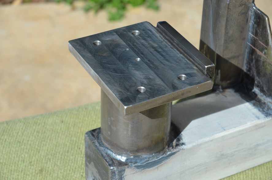
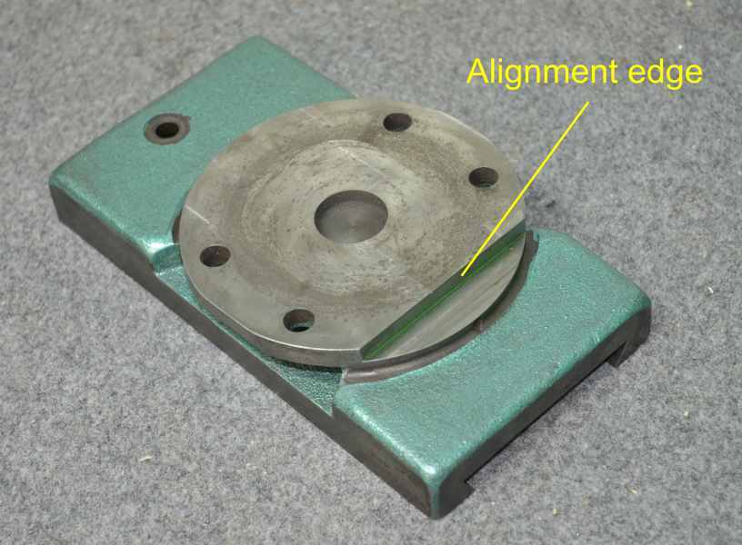
I have a cross slide that I kept from an old very worn lathe that I scrapped which was ideal for the traversing axis of the grinding head. I machined on shoulder on the bottom of the cross slide base which aligns on one of my fences. The other two mounting faces are for aluminium clamps to hold the wheel axles.
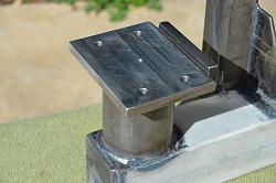
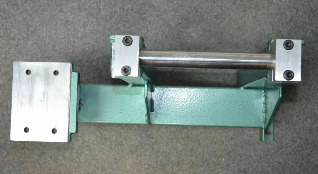
Here are shown the finished frame and the base of the cross slide with the machined alignment surface which locates against the fence on the frame.
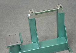
These two photos show a ground steel bar being used to check alignment of the wheel axle mountings.
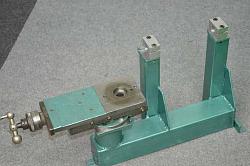
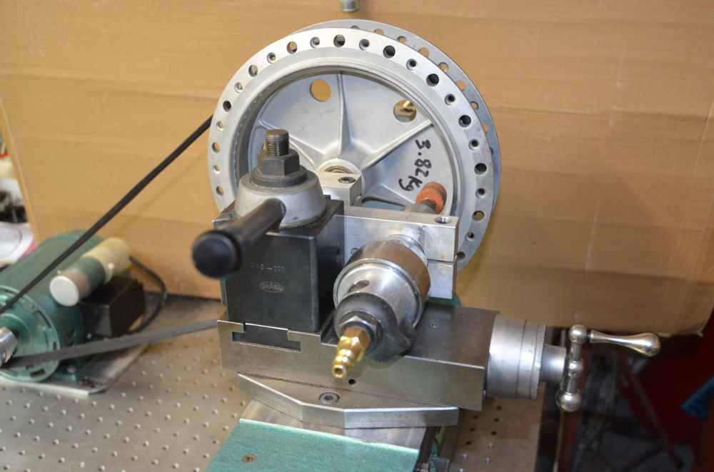
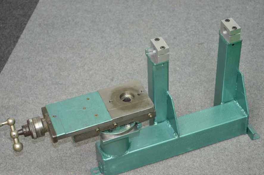
These pix. show the old cross slide mounted which is the first stage of the assembly. The other shows the cross slide and QD tool post temporarily borrowed from my working lathe. Also shown is the wheel mounting method.
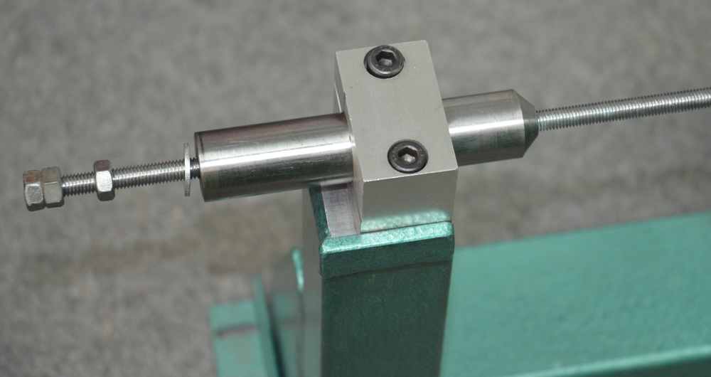
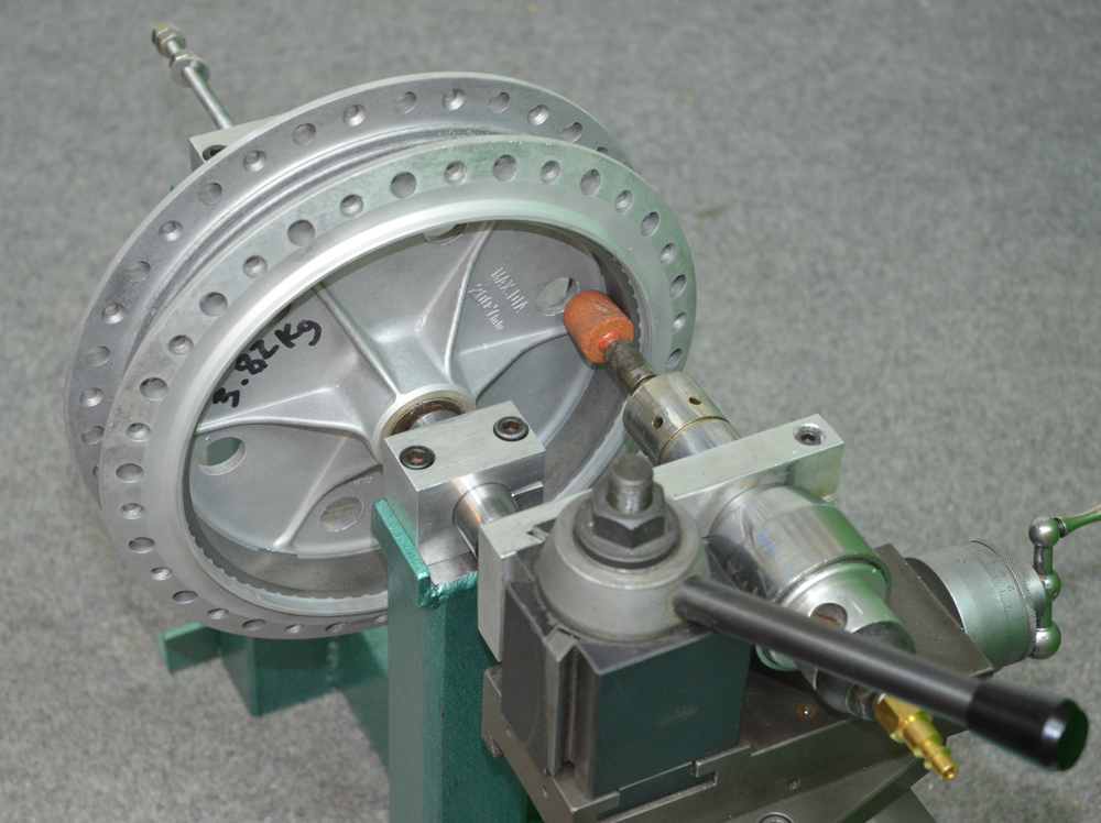
Detail of the wheel mounting. The wheel rotates about its own bearings and there are two of these tapered nose shafts which locate the bearings. The piece of All-Thread holds these shaft tight against the bearings. The shafts are 25mm. and so are suitable to cater for 15, 17 and 20mm bearings which are all that interest me.
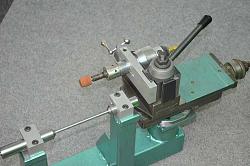
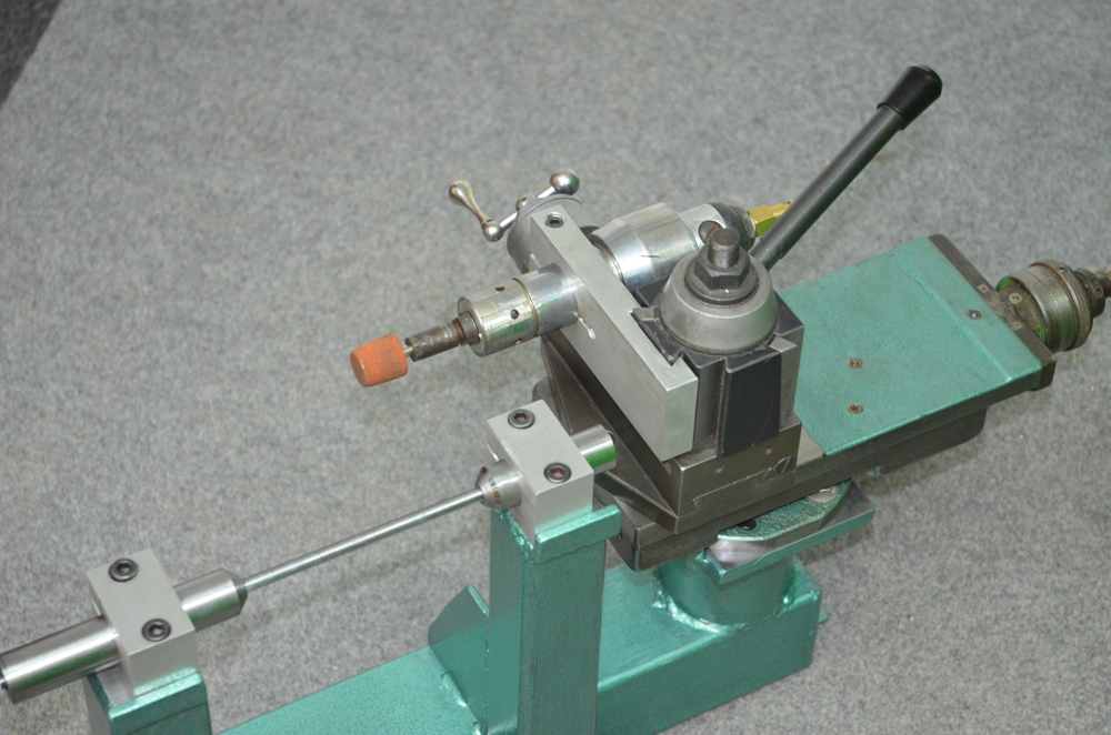
The grinding is done with mounted points driven by a high speed (30,000rpm) turbine style die grinder. That is mounted in a fixture for the QD tool post. I made the bracket to enable internal grinding on the lathe.
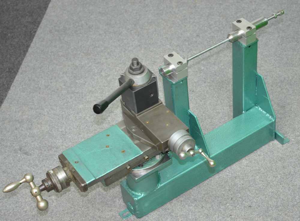
Here we see the finished tool set up ready to grind. The lower slide does the in and out traversing of the grinding head whilst the upper one at rt. angles adjust the depth of cut.
In practice the tool works really well and I can now set up drum brakes better than I have ever managed in the past. For those interested in optimising motorcycle drum brakes I developed some simple software to help design the important placement of the friction material on the shoes. This is important to get the right balance between a brake that grabs too fiercely and one that doesnt brake well enough. That software can be downloaded FOC from the Freeware section of my web site.
A tool like this can also be configured to do car drums as well as motorcycle ones. It is just a matter of making a shaft with a fixing plate for the drum and spinning the shaft between centres or adding bearings. Without too much modification it could also be used for discs.


 Reply With Quote

Bookmarks