After a recent disappointing purchase from Mkonto, I decided to give up on looking for what I wanted locally (prices for what I want from over the pond are just ridiculous), started some research, did some planning (mostly in my head), did a bit more research on materials, made a few phone calls and went shopping.
Its been a bit of a lengthy process to get to this point (been at it since November 2018) but I am progressing.
So the materials I have sourced are EN36 for the critical hard wearing part, and for the weight saving components, 6063 T6 Aluminium tube, and 6068 T6 Aluminium Round bar.
There are multiple threads (the screw kind) in this project, so went down to the local plastics supplier and rummaged through their scrap bin for suitable off-cuts to practice on. Having successfully mastered that, I began on the actual project. I unfortunately didn't take photos right from the beginning, but I have some to post here.
First part was to set the lathe up to be able to turn a 1.25mm Pitch thread. You basically just follow the thread/gear chart on the lathe and as long as you get it all right, you will have a 1.25mm pitch thread. Many lathes have a series of levers on the front to select the various gears to get the right spindle to leadscrew ratio. Unfortunately in my case, I have to do this manually and physically remove and change the gears in the gearbox every time I want to change the pitch. Gears were rearranged and the test was done on some of the offcut plastic.
Now to the body of the main unit, known as a Nielsen Device, sometimes referred to as a LID (Linear Inertia Decoupler) or a Booster, and here plenty of planning was involved. Its function is basically to decouple the barrel and suppressor while the action cycles to load the next round. The reason it is indexed is that normally the point of impact changes when a suppressor is fitted to the barrel. The indexing allows the point of impact to be adjusted to bring it closest to where it is supposed to be.
The entire project, 11 parts in all, need to be perfectly aligned once assembled. It was therefor imperative that once a piece of material is mounted and the cutting has begun, it not be disturbed in the chuck until it is complete.
The main body of the unit required 10 different tasks before it could be removed from the chuck. These were, in order of task:
1. Cutting the outer diameter
2. The straight knurl. This is done right at the beginning as it requires tremendous force on the part, and if it were going to move in the chuck, I wanted it to happen before any other critical parts were cut.
3. Cutting the rear diameter.
4. Cutting the taper to go from the rear diameter to the knurl.
5. Cutting the inner bore to size and depth.
6. Cutting the thread relief in the bore.
7. Cutting the internal thread.
8. Cutting the external thread major diameter
9. Cutting the thread relief for the external thread.
10. Cutting the forward relief
11. Cutting the external thread.
The part could then only be parted off and reversed to face off the other side. This is what the part looks like with the processes numbered.


The next part of the project was the body core, which slides inside the part above, but must be able to rotate, but must also be fixed, but must also be index-able!!!
This is what I came up with. It also has an internal thread. The outer surface is smooth and polished to ensure smooth action when doing what it is supposed to be doing. This part was actually turned out of a 30mm piece of EN36, without changing the outer diameter. It was then parted off and 8 holes drilled in a circle around the central hole. Once those were drilled, the part then went back into the lathe to have the larger diameter cut to fit snugly inside the bore of the body.


At this point I had to run off to the engineering shop as I had forgotten to drill the required offset hole in the material before I started. My good mate Johan popped in the milling machine and sorted it for me.

The hole would hold a pin, which would then locate into one of the holes drilled around the core. When pushed forward, this pin would lock the core, preventing it from turning. Once pulled back however, the core can turn and the pin would then locate in a different hole in the core.

Next up was the end cap for the main body of this piece.
When this photo was taken the part had just been through the blast cabinet in preparation for blackening

With the final result looking like this.


Then it was off to dig around in my favourite spring manufacturers over-run bins for a suitable spring to fit the core.
I found the perfect one. A little rusty when I got it but a quick run through the electroplating bath and it looks like new again.

The various parts lined up as they would be assembled.

Partly assembled


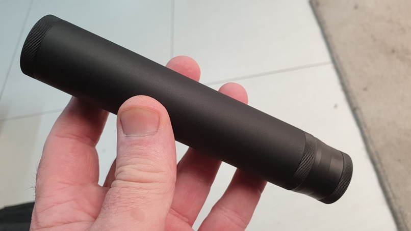
And the finished product.

Here it is fitted to the barrel without the suppressor attached.

With a suitable bolt turned into the core, this is how the unit will function.
Nielsen Device done! Now for the suppressor part.
First job was to put an Aluminium cap on the end of an Aluminium tube. So the tube was threaded internally first. The tube wall is 3mm thick, but much of that was removed as I needed the maximum capacity I could get on the inside of the tube.

Next was to make the cap to fit the tube. I didn't get the entire process, but here the cap is virtually complete.

And here the tube has been test fitted onto the cap whilst still in the chuck.

The inside of the cap was also bored out to save a little weight.

The semi completed cap.


And the completed cap just before anodizing

Then on to the innards. These just consist of a few fat washers curved on the one side and a few thin wall tube spacers.


That are assembled in this order.

The view inside the tube once everything is assembled.

Another view showing the baffles

And this is how they line up.

A view down the barrel

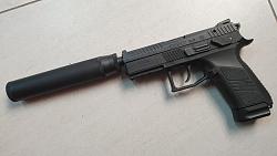
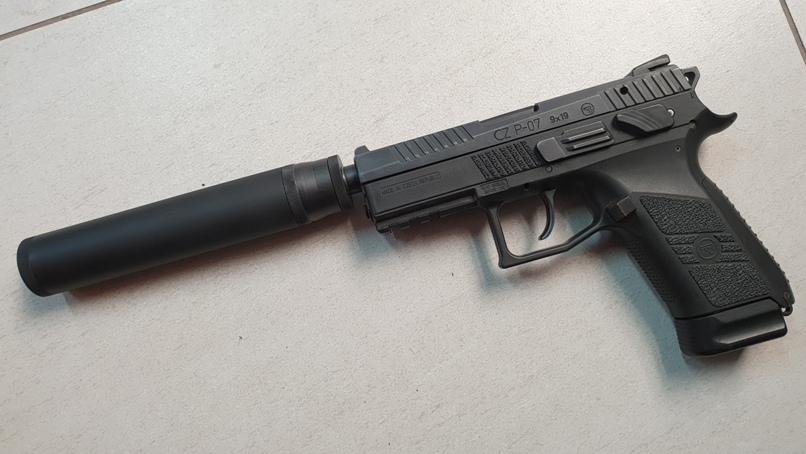
Completed and fitted.

Then it was off to the range.
Test firing. First, without the suppressor. Camera is about 2 meters away while firing.
Next the disappointing purchase from Mkonto. That thing is HUGE! Camera in the same position.
Then my handywork. Here the camera is up close. I must admit, I am rather happy with that!
 LinkBack URL
 About LinkBacks


Originally Posted by dbat74


, started some research, did some planning (mostly in my head), did a bit more research on materials, made a few phone calls and went shopping.
Its been a bit of a lengthy process to get to this point (been at it since November 2018) "Pin It")

 Posting Permissions


 Reply With Quote
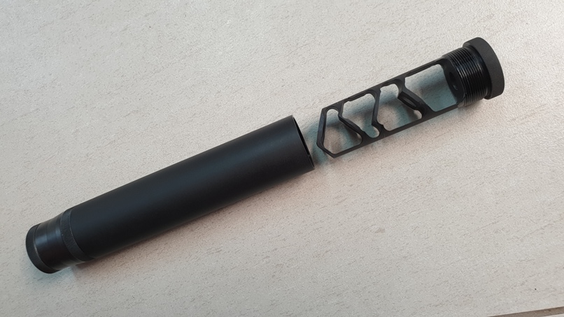
Bookmarks