Free 186 More Best Homemade Tools eBook:  
New: 300+ fresh build posts/day from 275 forums → BuildThreads.com

User Tag List

Results 1 to 10 of 14

Thread: Method for setting vee block centrally to machine spindle

Threaded View

  1. #1
    Supporting Member thehomeengineer's Avatar
    Join Date
    Nov 2017
    Location
    Berkshire UK
    Posts
    762
    Thanks
    764
    Thanked 2,388 Times in 483 Posts

    thehomeengineer's Tools

    Method for setting vee block centrally to machine spindle

    Hi All

    This is the method I use for setting a vee block centrally to machine spindle.
    This is a quick method for setting up a vee block centrally to the machine spindle, be it a on a drill or mill.

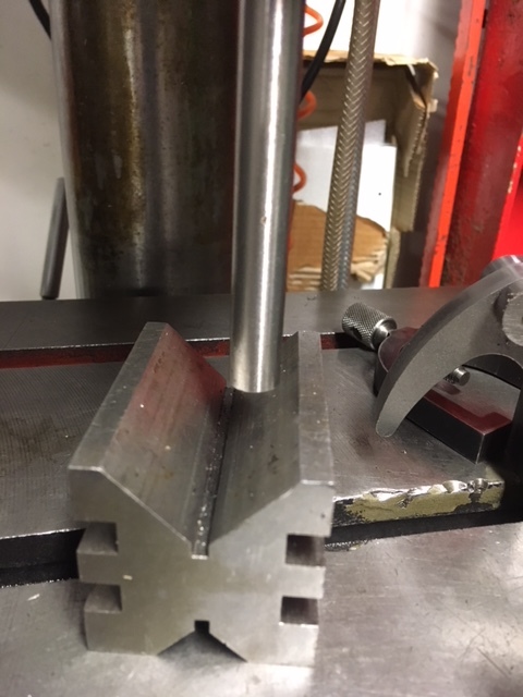
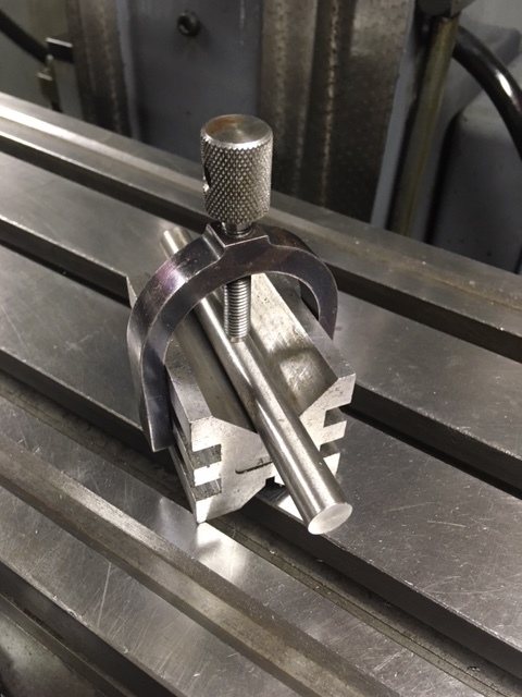
    The first picture shows a piece of material which has been machined square in the lathe and is the setting piece.

    Click image for larger version. 

Name:	IMG_0509.JPG 
Views:	1244 
Size:	95.8 KB 
ID:	21614

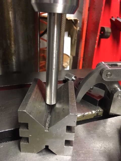
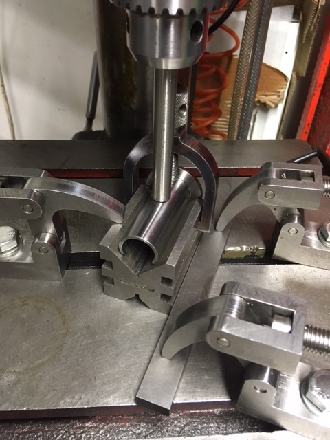
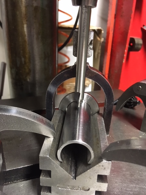
    The second photo shows the setting bar being lowered in to the vee of the block using the machines quill. This centralises the vee block to the spindle.

    Click image for larger version. 

Name:	IMG_0510.JPG 
Views:	690 
Size:	98.6 KB 
ID:	21615

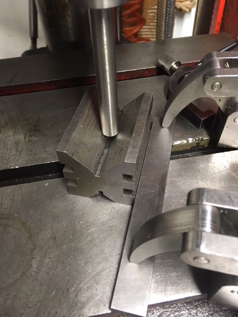
    The third photo shows a parallel being clamped against the base of the vee block. This needs to be tighten and square to the block.

    Click image for larger version. 

Name:	IMG_0511.JPG 
Views:	690 
Size:	109.2 KB 
ID:	21616

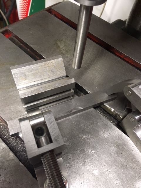
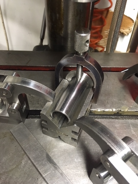
    The forth photo shows the vee block being moved along the parallel. This enables the work piece to be position without machining into the vee block but still maintaining the central position. (In this case I didn’t need to use the parallel as it is a piece of tube and I am only drill one side of the wall.

    Click image for larger version. 

Name:	IMG_0512.JPG 
Views:	652 
Size:	127.7 KB 
ID:	21617

    The fifth photo shows the clamping of the vee block to the table, the left clamp is operated first with the vee block still against the clamped parallel to ensure the position is maintained.

    Click image for larger version. 

Name:	IMG_0513.JPG 
Views:	786 
Size:	121.7 KB 
ID:	21618

    The sixth photo shows the parallel removed and the second clamp in position to ensure good clamping of the vee block.

    Click image for larger version. 

Name:	IMG_0514.JPG 
Views:	721 
Size:	114.9 KB 
ID:	21619

    The seventh photo shows the centre drill ready to drill the component on its centre line.

    Click image for larger version. 

Name:	IMG_0515 - Copy.JPG 
Views:	708 
Size:	103.5 KB 
ID:	21620

    The setting bar is also used to clamp the vee block and horse shoe clamp together for storing.

    Click image for larger version. 

Name:	IMG_0516.JPG 
Views:	670 
Size:	114.1 KB 
ID:	21632

    This isn’t a home-made tool but I hope you have found this useful for any future projects you where you might need to drill on the centre line of a shaft.

    The Home Engineer
    Last edited by thehomeengineer; Jan 20, 2018 at 02:04 AM.

  2. The Following 21 Users Say Thank You to thehomeengineer For This Useful Post:

    Andyt (Feb 26, 2020), astroscuba (Aug 19, 2023), Captainleeward (Jan 20, 2018), davesrepair (Aug 6, 2024), Eaglewood (Nov 17, 2022), emu roo (Nov 17, 2022), Harvey Melvin Richards (May 24, 2018), JD62 (Jan 20, 2018), Jon (Jan 20, 2018), metric_taper (Jan 20, 2018), Moby Duck (Jan 20, 2018), mr mikey (Jul 19, 2022), Philip Davies (Feb 26, 2020), PJs (Jan 28, 2018), RetiredFAE (Jul 18, 2022), Seedtick (Jan 20, 2018), that_other_guy (Aug 18, 2023), Tonyg (Feb 26, 2020), Toolmaker51 (Nov 18, 2022), trevor_60_r (Nov 18, 2022), Z2V (May 24, 2018)

Thread Information

Users Browsing this Thread

There are currently 1 users browsing this thread. (0 members and 1 guests)

Bookmarks

Posting Permissions

  • You may not post new threads
  • You may not post replies
  • You may not post attachments
  • You may not edit your posts
  •