Free 186 More Best Homemade Tools eBook:  
New: 300+ fresh build posts/day from 275 forums → BuildThreads.com

User Tag List

Page 1 of 2 1 2 LastLast
Results 1 to 10 of 21

Thread: rotary table driven by stepper motor controlled by 2 Arduino's

Hybrid View

  1. #1
    Supporting Member thehomeengineer's Avatar
    Join Date
    Nov 2017
    Location
    Berkshire UK
    Posts
    763
    Thanks
    764
    Thanked 2,390 Times in 484 Posts

    thehomeengineer's Tools

    rotary table driven by stepper motor controlled by 2 Arduino's

    hi All
    I have finally attached the stepper motor and encoder and had the rotary table moving.
    After testing there are a couple of issue that need attention 1st being the variable feed/speed control via a potentiometer. When turned to full rotation it stalls the motor. 2nd I need to check the coupling is tight on the motor shaft and the control box wiring is somewhat messy and will need tidying but as this is the first time I have ever taken on a project like this. It was very much a, make it up as you go along just to get it working and then worry about the presentation at the end.

    The main control is via a Arduino Mega and TB6600 motor controller and the encoder uses a Arduino Nano.

    I did have a lot of help with the programming. Without this help, I don't think I would have completed the project with all the features I wanted.

    The control box has four modes. Degrees, Divisions, Jog and Feed. The Feed is controlled via a potentiometer, which I want to change how this controls the table.

    rotary table driven by stepper motor controlled by 2 Arduino's-wiring.jpg 
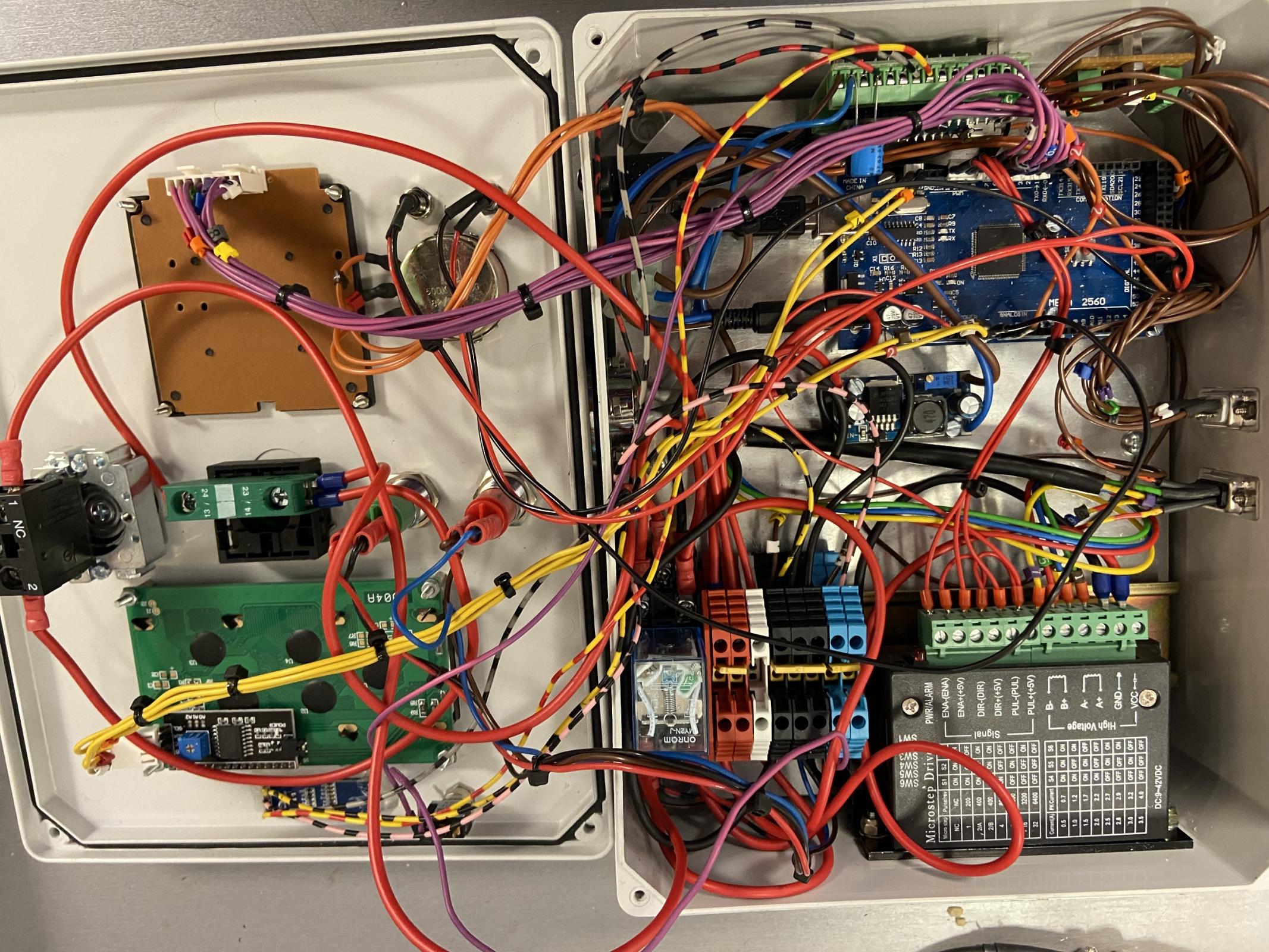
Needs a little tidying
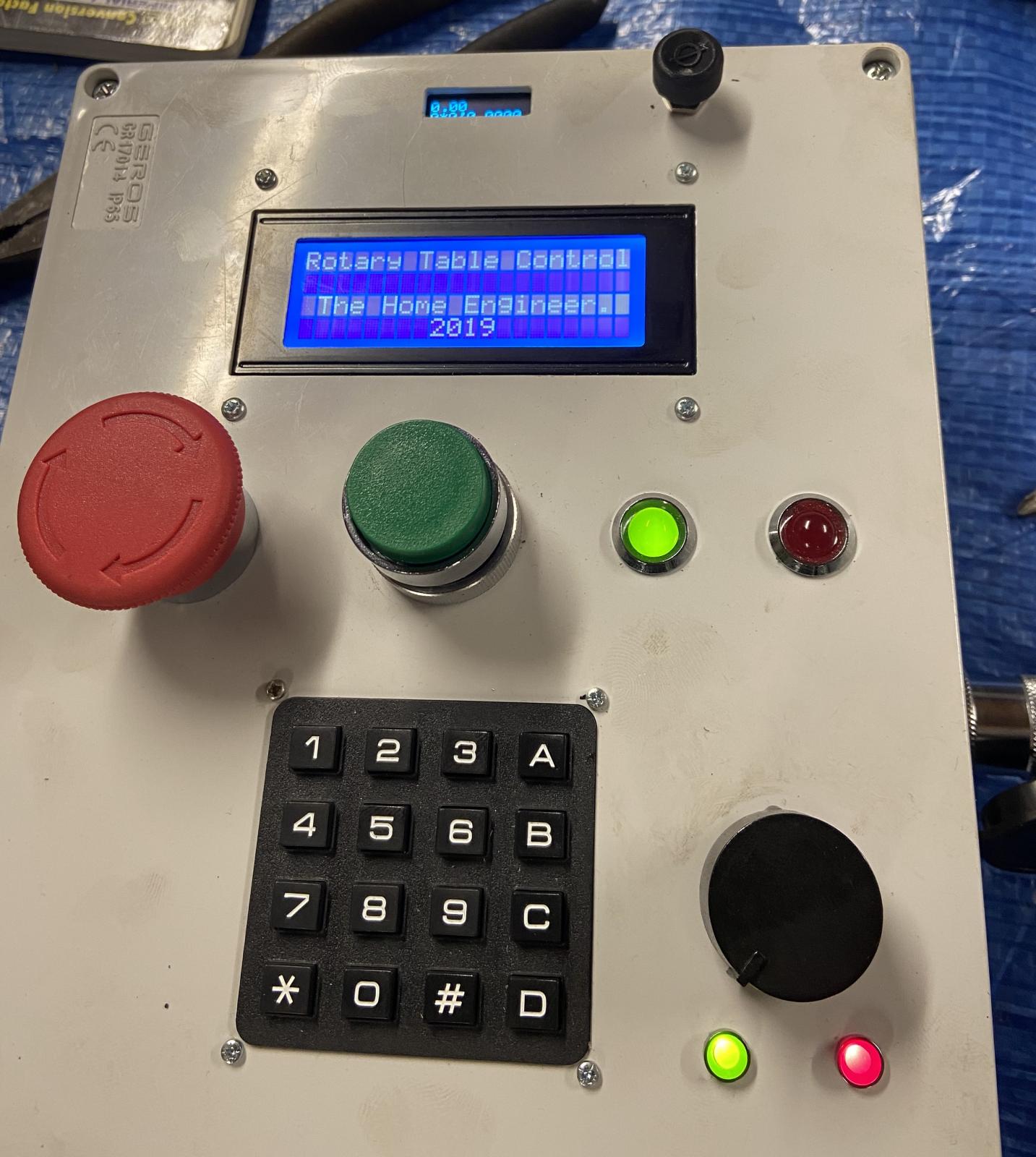
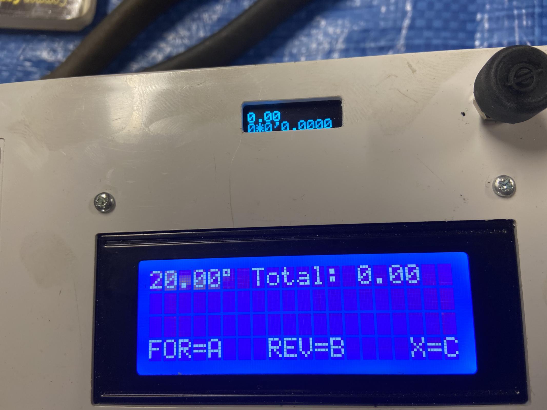
    rotary table driven by stepper motor controlled by 2 Arduino's-setup-sequence.jpg Start up

    rotary table driven by stepper motor controlled by 2 Arduino's-options.jpg 
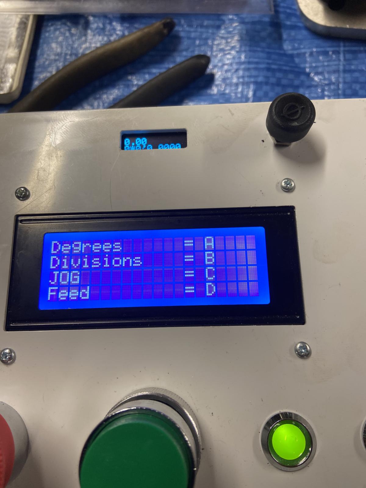
Options that can be selected
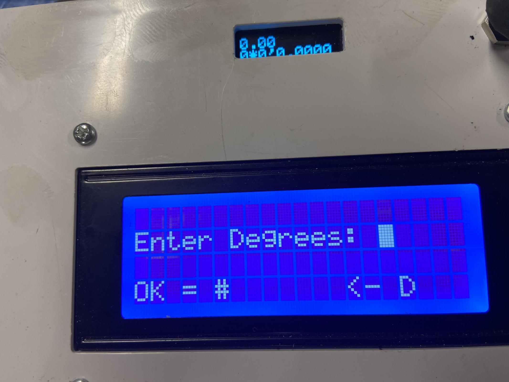
    rotary table driven by stepper motor controlled by 2 Arduino's-selection.jpg Degrees selected

    rotary table driven by stepper motor controlled by 2 Arduino's-ready.jpg 
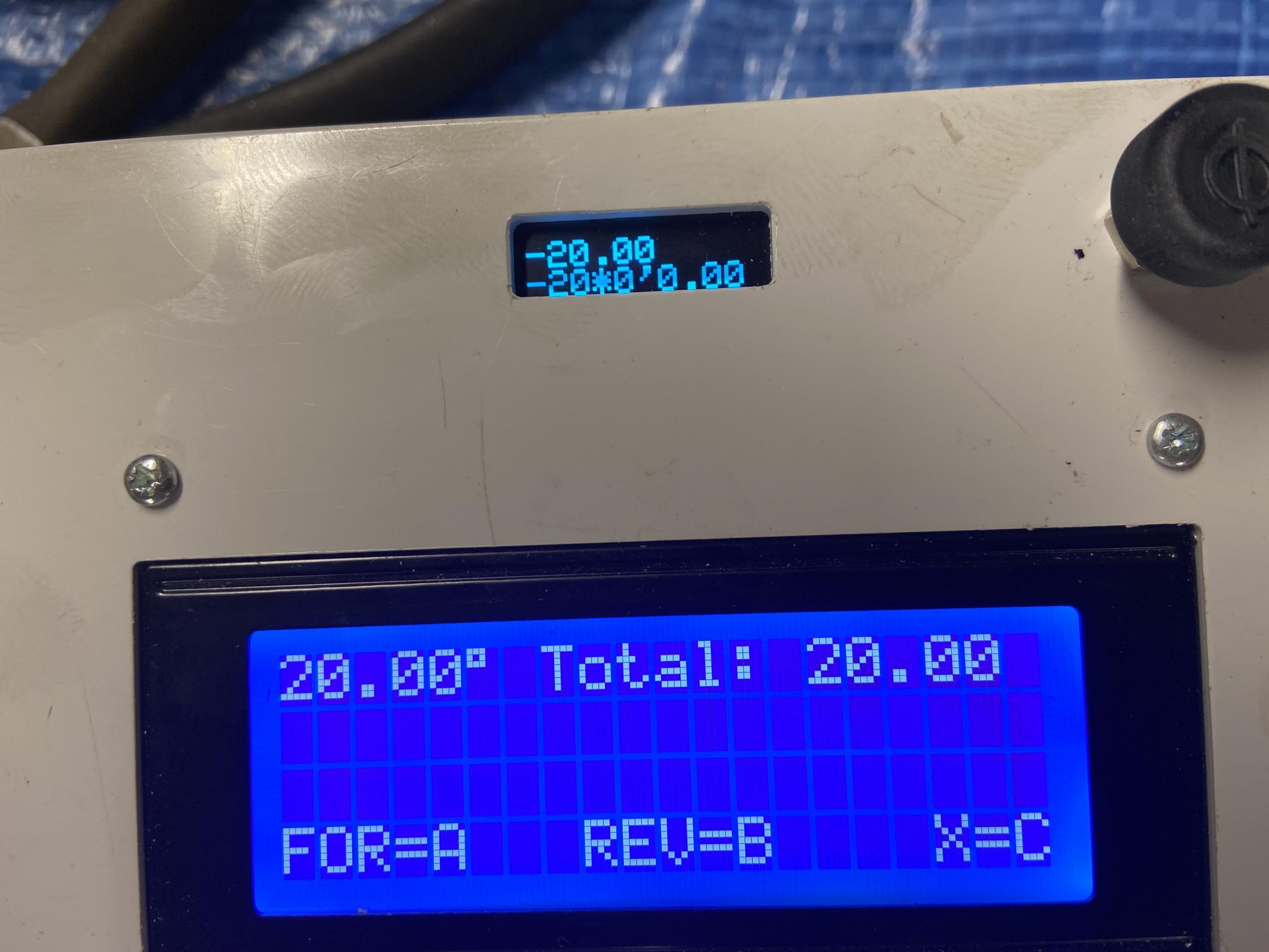
Selection set to 20 degrees and ready to move table.

    rotary table driven by stepper motor controlled by 2 Arduino's-travelled.jpg Angle travelled and small top screen shows position via encoder. Very pleased with accuracy.

    rotary table driven by stepper motor controlled by 2 Arduino's-stepper-motor-adaptor-plate.jpg 
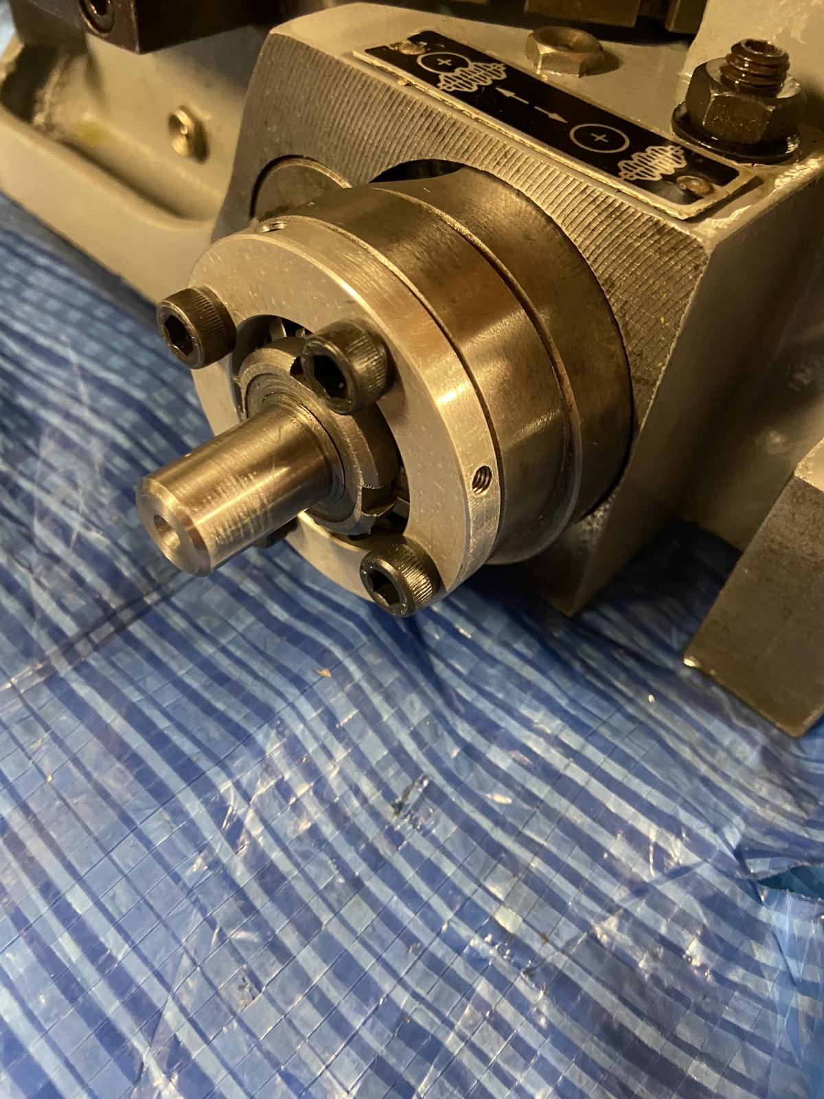
Aluminium adaptor plate to connect stepper motor to table

    rotary table driven by stepper motor controlled by 2 Arduino's-stepper.jpg rotary table driven by stepper motor controlled by 2 Arduino's-motor-inplace.jpg 
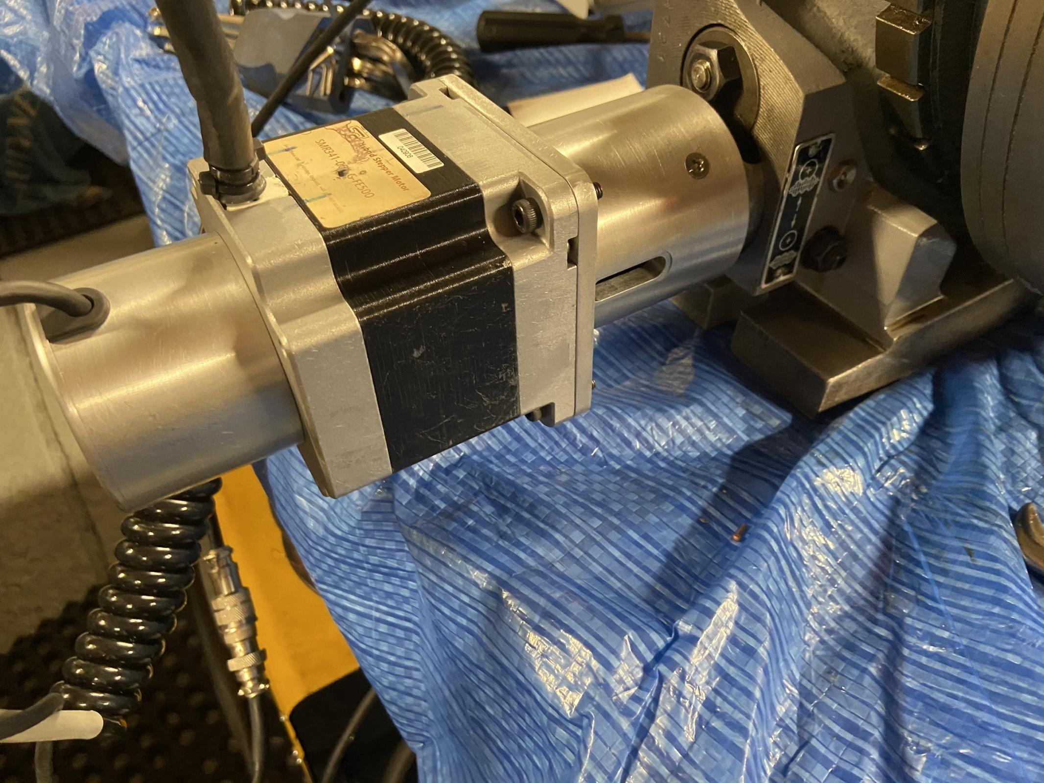
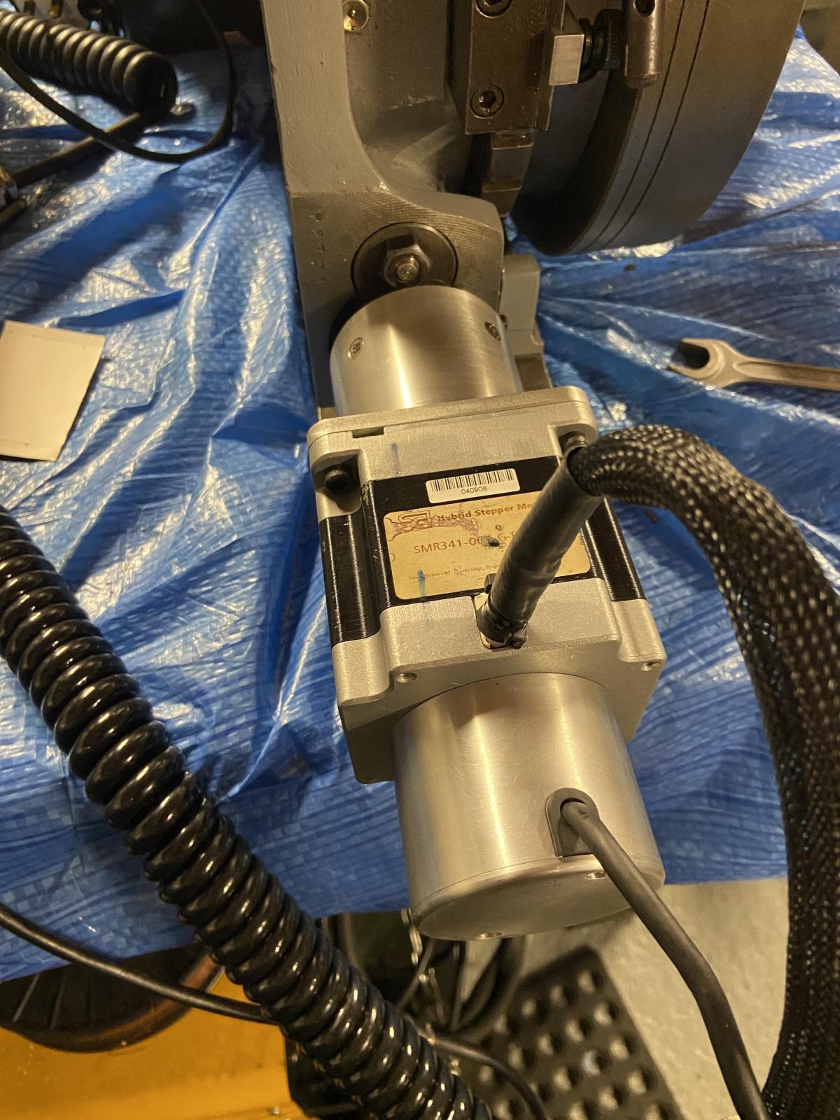
Motor and encoder in place

    This project was a steep learning curve with many mistakes made some expensive It has been very interesting and frustrating at the same time, but as previously mentioned without the help of a very clever electronics apprentice where I work, I would have struggled to complete this project. So a massive thank you to him.

    I have added some links below which are also linked to this project which I think has been roughly a 6 months in the making.

    Links:
    https://www.homemadetools.net/forum/rotary-table-re-ferb-ready-stepper-motor-75765

    rotary table worm shaft
    Comparing worm shaft depth with three wire method
    Rotary table stepper motor encoder mounting plate and encoder bore reducer
    Stepper motor encoder cover

    Thank you for taking the time to view.

    The Home Engineer

  2. The Following 18 Users Say Thank You to thehomeengineer For This Useful Post:

    albertq (Mar 22, 2024), bobs409 (Jan 14, 2020), byates (Jun 1, 2023), DIYSwede (Jan 10, 2020), Duke_of_URL (May 29, 2023), emu roo (Jul 20, 2022), garage nut (Jan 11, 2020), high-side (Jan 13, 2020), Home-PC (May 30, 2023), Jon (Jan 10, 2020), Mr Mechanical (Jan 14, 2020), mwmkravchenko (Jan 13, 2020), Paul Jones (Jan 15, 2020), Ralphxyz (Jul 24, 2022), Saltfever (Jan 20, 2020), schatten (Jan 14, 2020), tonyfoale (Jul 21, 2022), Tonyg (Jan 16, 2020)

  3. #2
    Supporting Member garage nut's Avatar
    Join Date
    Jul 2017
    Location
    Port Elizabet, SA
    Posts
    246
    Thanks
    92
    Thanked 464 Times in 115 Posts

    garage nut's Tools
    Please make the code available.

  4. The Following User Says Thank You to garage nut For This Useful Post:

    emu roo (Sep 25, 2025)

  5. #3
    Supporting Member thehomeengineer's Avatar
    Join Date
    Nov 2017
    Location
    Berkshire UK
    Posts
    763
    Thanks
    764
    Thanked 2,390 Times in 484 Posts

    thehomeengineer's Tools
    Rotary table code Used on Arduino Mega


    #include <Wire.h>
    #include <Keypad.h>
    #include <LiquidCrystal_I2C.h>
    //#include <I2CScanner.h>


    const byte ROWS = 4;
    const byte COLS = 4;
    //****************USER DEFINED**************
    //setup vars
    const int stp = 10; // connect pin D10 to step
    const int dir = 11; // connect pin D11 to dir
    const int StepsPerRotation = 1600; // Set Steps per rotation of stepper NOTE the driver is set to Half step
    const int TableRatio = 90; // ratio of rotary table
    const int stepdelay = 1000; //this is in microseconds
    int delay1 = 2000; //this is used for Splash Screen display time
    byte colPINS[ROWS] = {2, 3, 4, 5}; //pin 1 of keypad to pin 12
    byte rowPINS[COLS] = {6, 7, 8, 9};
    int pot = A0; //potentiometer wiper
    int pot_movement = 0;
    int pot_movement_mapped = 0;
    int adj_speed = 3000; //Speed adjustment (Max mapped uS) Making this LOWER will INCREASE min RPM, making this HIGHER will DECREASE min RPM
    int feed_pot_thresh=5; //Adjust this variable to change when the potentiometer makes the motor move (bigger means more movement to initialise motor)
    int inc = 0;
    int ledbrightness = 120;
    int led_inc = 0;
    int ind_green = 44;
    int ind_red = 46;
    LiquidCrystal_I2C lcd(0x27, 20, 4); // set the LCD address as determined by I2C scanner


    /*
    byte degss[] = {
    B00100,
    B01110,
    B01110,
    B01110,
    B11111,
    B00000,
    B00100,
    B00000
    };
    */


    // SCL - A5, SDA - A4, VCC - +5, Gnd - Gnd
    //***********************************************


    // **************define Debug Macro**************
    //#define DEBUG 1 //delete slashes for printing debug info to serial monitor
    #ifdef DEBUG
    #define DEBUG_Print(x) Serial.print(x)
    #define DEBUG_PrintDec(x,y) Serial.print(x,y)
    #define DEBUG_Println(x) Serial.println(x)
    #else
    #define DEBUG_Print(x)
    #define DEBUG_PrintDec(x,y)
    #define DEBUG_Println(x)
    #endif


    char keys[ROWS][COLS] = {
    {'1', '2', '3', 'A'},
    {'4', '5', '6', 'B'},
    {'7', '8', '9', 'C'},
    {'.', '0', '#', 'D'}
    };


    Keypad kpd = Keypad(makeKeymap(keys), rowPINS, colPINS, ROWS, COLS);


    int moved;
    long Multiplier;
    long cumSteps = 0;
    float Degrees = 0.; // Degrees from keypad
    long ToMove = 0; // Steps to move


    float bob = 0.; //this tracks current position in degrees


    int cho = 0;


    void setup()
    {
    //lcd.createChar(0, degss);


    #ifdef DEBUG
    Serial.begin(9600);
    #endif
    Multiplier = (long)TableRatio * StepsPerRotation;
    lcd.init(); // initialize the lcd


    pinMode(stp, OUTPUT);
    pinMode(dir, OUTPUT);


    // Print welcome message to the LCD.
    lcd.backlight();
    lcd.print("Rotary Table Control");
    lcd.setCursor(1, 2);
    lcd.print("The Home Engineer.");
    lcd.setCursor(8, 3);
    lcd.print("2019");
    //delay1 = 500;
    //delay (delay1);


    // fade in from min to max in increments of 5 points - indicator LEDs:
    while (led_inc != 2) {
    for (int fadeValue = 0 ; fadeValue <= 255; fadeValue += 5) {
    // sets the value (range from 0 to 255):
    analogWrite(ind_green, fadeValue);
    analogWrite(ind_red, fadeValue);
    // wait for 30 milliseconds to see the dimming effect
    delay(30);
    }


    // fade out from max to min in increments of 5 points:
    for (int fadeValue = 255 ; fadeValue >= 0; fadeValue -= 5) {
    // sets the value (range from 0 to 255):
    analogWrite(ind_green, fadeValue);
    analogWrite(ind_red, fadeValue);
    // wait for 30 milliseconds to see the dimming effect
    delay(30);
    }
    led_inc = (led_inc + 1);
    }
    digitalWrite(ind_red, HIGH);
    digitalWrite(ind_green, LOW);
    lcd.init();
    cho = 0;
    // *************************************************


    char key = kpd.getKey();
    lcd.print("Degrees "); lcd.print(" = A");
    lcd.setCursor(0, 1);
    lcd.print("Divisions = B");
    lcd.setCursor(0, 2);
    lcd.print("JOG = C");
    lcd.setCursor(0, 3);
    lcd.print("Feed = D");


    while (cho == 0)
    {
    key = kpd.getKey();
    switch (key)
    {
    case NO_KEY:
    break;
    case 'A':
    Degrees = getdegrees();
    lcd.clear();
    cho = 1;
    break;
    case 'B':
    Degrees = getdivisions();
    cho = 2;
    break;
    case 'C':
    Degrees = getjog();
    lcd.clear();
    cho = 3;
    break;
    case 'D':
    Degrees = getfeed();
    lcd.clear();
    cho = 4;
    break;


    } // end case
    } // end while cho=0
    DEBUG_Print("90 = 1"); DEBUG_Println(TableRatio);
    DEBUG_Print("800 = 1"); DEBUG_Println(StepsPerRotation);
    DEBUG_Print("800 = 360"); DEBUG_Println(Multiplier);


    } // end setup


    void loop() // MAIN LOOP
    {
    lcd.clear();
    char key = kpd.getKey();
    bob = 0;


    cumSteps = 0;
    lcd.setCursor(7, 0); lcd.print("Total: "); lcd.print(" "); lcd.setCursor(14, 0); lcd.print(bob, 2); // total steps


    lcd.setCursor(0, 3); lcd.print("FOR=A REV=B X=C");
    while (key != 'C') // C will return to start menu
    {
    lcd.setCursor(0, 0); lcd.print(abs(Degrees), 2); lcd.print((char)223);
    key = kpd.getKey();
    if (key == 'A') // FORWARD
    {


    bob = bob + Degrees;


    ToMove = (bob * Multiplier) / 360 + 0.5 - cumSteps;


    cumSteps = cumSteps + ToMove;


    digitalWrite(dir, LOW);
    printadvance();


    }
    if (key == 'B') // REVERSE
    {


    bob = bob - Degrees;
    ToMove = -1*((bob * Multiplier) / 360 + 0.5 - cumSteps);


    cumSteps = cumSteps - ToMove;


    digitalWrite(dir, HIGH); // pin 13
    printadvance();
    }
    } // end while not C loop
    lcd.init();
    setup();
    } // end main VOID


    float getjog() // used to set mechanical ratio and steps per revolution
    {
    digitalWrite(ind_red, HIGH);
    digitalWrite(ind_green, LOW);
    float Degrees = 0;
    float num = 0.00;
    char key = kpd.getKey();
    lcd.clear();
    lcd.setCursor(6, 0); lcd.print("Jogging");
    lcd.setCursor(0, 1); lcd.print("A=0.5 B=1 C=5 Deg's ");
    lcd.setCursor(0, 2); lcd.print("Choose Degrees:"); lcd.setCursor(0, 3); lcd.print("OK = # "); lcd.print((char)60); lcd.print((char)45); lcd.print(" D");


    while (key != '#')
    {
    switch (key)
    {
    case NO_KEY:
    break;
    case 'A':
    Degrees = 0.5;
    lcd.setCursor(16, 2); lcd.print(Degrees, 1);
    break;
    case 'B':
    Degrees = 1;
    lcd.setCursor(16, 2); lcd.print(Degrees, 1);
    break;
    case 'C':
    Degrees = 5;
    lcd.setCursor(16, 2); lcd.print(Degrees, 1);
    break;
    case 'D':
    num = 0.00;
    lcd.setCursor(15, 2); lcd.print(" ");
    lcd.setCursor(15, 2);
    break;
    }
    key = kpd.getKey();
    }
    return Degrees;
    }


    float getdivisions()
    {
    digitalWrite(ind_green, HIGH);
    digitalWrite(ind_red, LOW);
    lcd.noBlink();
    float Degrees = 0;
    float num = 0.00;
    char key = kpd.getKey();
    lcd.clear();
    lcd.blink();
    lcd.setCursor(0, 1); lcd.print("Enter Division:");
    lcd.setCursor(0, 3); lcd.print("OK = # ");
    lcd.print((char)60); lcd.print((char)45); lcd.print(" D");
    lcd.setCursor(16, 1);


    while (key != '#')
    {
    switch (key)
    {
    case NO_KEY:
    break;


    case '0': case '1': case '2': case '3': case '4':
    case '5': case '6': case '7': case '8': case '9':
    num = num * 10 + (key - '0');
    lcd.print(key);
    break;


    case 'D':
    num = 0.00;
    lcd.setCursor(16, 1); lcd.print(" ");
    lcd.setCursor(16, 1);
    break;
    }
    Degrees = 360 / num;
    key = kpd.getKey();
    }
    return Degrees; //num;
    }


    float getfeed()
    {
    digitalWrite(ind_green, HIGH);
    digitalWrite(ind_red, LOW);
    lcd.noBlink();
    //int key = 0;
    float num = 0.00;
    float decimal = 0.00;
    float decnum = 0.00;
    int counter = 0;
    lcd.clear();
    //lcd.init();
    lcd.setCursor(2, 0);
    lcd.print("Use potentiometer");
    lcd.setCursor(2, 1);
    lcd.print("to set the speed");
    lcd.setCursor(5, 2);
    lcd.print("of rotation");
    delay(1500);
    lcd.clear();


    char key = kpd.getKey();
    lcd.setCursor(0, 1); lcd.print("Enter Degrees:"); lcd.setCursor(0, 3); lcd.print("OK = # "); lcd.print((char)60); lcd.print((char)45); lcd.print(" D");
    lcd.setCursor(15, 1);
    lcd.blink();
    bool decOffset = false;


    while (key != '#')
    {
    switch (key)
    {
    case NO_KEY:
    break;


    case '.':
    if (!decOffset)
    {
    decOffset = true;
    }
    lcd.print(key);
    break;


    case 'D':
    num = 0.00;
    lcd.setCursor(15, 1); lcd.print(" ");
    lcd.setCursor(15, 1);
    break;


    case '0': case '1': case '2': case '3': case '4':
    case '5': case '6': case '7': case '8': case '9':
    if (!decOffset)
    {
    num = num * 10 + (key - '0');
    lcd.print(key);
    }
    else if ((decOffset) && (counter <= 1))
    {
    num = num * 10 + (key - '0');
    lcd.print(key);
    counter++;
    }
    break;
    } //end case
    decnum = num / pow(10, counter);
    key = kpd.getKey();
    } //end while not #
    return decnum;
    } // end getdegrees


    float getdegrees()
    {
    digitalWrite(ind_red, HIGH);
    digitalWrite(ind_green, LOW);
    lcd.noBlink();
    //int key = 0;
    float num = 0.00;
    float decimal = 0.00;
    float decnum = 0.00;
    int counter = 0;
    lcd.clear();
    //lcd.init();
    char key = kpd.getKey();
    lcd.blink();
    lcd.setCursor(0, 1); lcd.print("Enter Degrees:"); lcd.setCursor(0, 3); lcd.print("OK = # "); lcd.print((char)60); lcd.print((char)45); lcd.print(" D");
    lcd.setCursor(15, 1);
    bool decOffset = false;


    while (key != '#')
    {
    switch (key)
    {
    case NO_KEY:
    break;


    case '.':
    if (!decOffset)
    {
    decOffset = true;
    }
    lcd.print(key);
    break;


    case 'D':
    num = 0.00;
    lcd.setCursor(15, 1); lcd.print(" ");
    lcd.setCursor(15, 1);
    break;


    case '0': case '1': case '2': case '3': case '4':
    case '5': case '6': case '7': case '8': case '9':
    if (!decOffset)
    {
    num = num * 10 + (key - '0');
    lcd.print(key);
    }
    else if ((decOffset) && (counter <= 1))
    {
    num = num * 10 + (key - '0');
    lcd.print(key);
    counter++;
    }
    break;
    } //end case
    decnum = num / pow(10, counter);
    key = kpd.getKey();
    } //end while not #
    return decnum;
    } // end getdegrees


    void printadvance() // print function
    {
    lcd.noBlink();
    lcd.setCursor(6, 1); lcd.print("Moving");
    lcd.setCursor(14, 0); lcd.print(bob, 2);
    rotation(ToMove, 0);
    lcd.setCursor(6, 1); lcd.print(" ");
    }


    void rotation(long tm, int d)
    {
    DEBUG_Print("Total Degrees = "); DEBUG_PrintDec(bob, 3); DEBUG_Print(" Steps to move = "); DEBUG_Print(tm); DEBUG_Print(" Total Steps = "); DEBUG_Println(cumSteps);


    if (cho == 4 || cho == 2) {
    for (long i = 0; i < tm; i++) //tm == To Movement
    {
    //pot_movement = analogRead(pot);
    pot_movement_mapped = map (analogRead(pot), 0, 1023, 0, adj_speed);
    if(pot_movement_mapped<(adj_speed-feed_pot_thresh)){//only move if the pot is above a threshold
    digitalWrite(stp, HIGH);
    delayMicroseconds(pot_movement_mapped);
    digitalWrite(stp, LOW);
    delayMicroseconds(pot_movement_mapped);
    }
    else{//decrement i if the motor hasn't been moved to ensure full motion is acheived
    i--;
    }
    }
    }
    else {
    for (long i = 0; i < tm; i++) //tm == Total Movement
    {
    digitalWrite(stp, HIGH);
    delayMicroseconds(stepdelay);
    digitalWrite(stp, LOW);
    delayMicroseconds(stepdelay);
    }


    }
    }


    void software_Reset() // Restarts program from beginning but does not reset the peripherals and registers
    {
    asm volatile (" jmp 0");
    }
    Last edited by thehomeengineer; Jan 13, 2020 at 07:13 AM.

  6. The Following 7 Users Say Thank You to thehomeengineer For This Useful Post:

    brianr47 (Jan 27, 2025), byates (Jun 1, 2023), emu roo (Sep 25, 2025), fizzloid (Jul 21, 2022), Home-PC (May 30, 2023), Jon (Jan 17, 2020), Paul Jones (Jan 15, 2020)

  7. #4
    Supporting Member thehomeengineer's Avatar
    Join Date
    Nov 2017
    Location
    Berkshire UK
    Posts
    763
    Thanks
    764
    Thanked 2,390 Times in 484 Posts

    thehomeengineer's Tools
    Hi Garage Nut
    I have posted the code on HMT (above)
    Please note I am sure there is a better way to programme but this is my first attempt. If improvements can be made to both codes I would be interested as this is been a long and sometimes frustrating, step learning curve for me and it has taken well over six months to get it to finally work. Lots of help and research on the net to try and understand C+ code. This was suppose to be a simple index project but grow and grow as I realised what could be achieved with the Arduino. I am more than happy for members on HMT to rip the code apart and tell me how I could improve or made it better. I feel the programming is as messy as the wiring in the control box but it does work.
    The Home Engineer

  8. The Following 2 Users Say Thank You to thehomeengineer For This Useful Post:

    emu roo (Sep 25, 2025), schatten (Jun 1, 2023)

  9. #5
    Supporting Member tonyfoale's Avatar
    Join Date
    Nov 2016
    Location
    Spain
    Posts
    1,821
    Thanks
    834
    Thanked 3,242 Times in 910 Posts

    tonyfoale's Tools
    Quote Originally Posted by thehomeengineer View Post
    Hi Garage Nut
    I have posted the code on HMT (above).......... I am more than happy for members on HMT to rip the code apart and tell me how I could improve or made it better. I feel the programming is as messy as the wiring in the control box but it does work.
    The Home Engineer
    I do not have the time to go through your code in detail, but my initial impression was that the Mega code was very long for the tasks. I might think differently if I waded through it all.

    You last function "software_Reset()" is defined but a search did not find any instances of it being called.

    The posted Nano code looks to be missing a chunk. As posted it does nothing.
    You attach an interrupt "attachInterrupt(0, runEncoder1, RISING );" but there is no "runEncoder1()".

  10. #6
    Supporting Member thehomeengineer's Avatar
    Join Date
    Nov 2017
    Location
    Berkshire UK
    Posts
    763
    Thanks
    764
    Thanked 2,390 Times in 484 Posts

    thehomeengineer's Tools
    Encoder Arduino code using Arduino Nano


    #include <SPI.h>
    #include <Adafruit_GFX.h>
    #include <Adafruit_SSD1306.h>
    #include <Wire.h>


    #define SCREEN_WIDTH 128 // OLED display width, in pixels
    #define SCREEN_HEIGHT 32 // OLED display height, in pixels


    // Declaration for an SSD1306 display connected to I2C (SDA, SCL pins)
    #define OLED_RESET 4 // Reset pin # (or -1 if sharing Arduino reset pin)
    Adafruit_SSD1306 display(SCREEN_WIDTH, SCREEN_HEIGHT, &Wire, OLED_RESET);


    const byte interrupt = 2;
    const byte interruptB = 3;
    const int encoder1PinA = 2; // encoder channel A,B (interupt pins)
    const int encoder1PinB = 3;
    float Pos1deg = 0;


    volatile float encoder1Pos = 0; //ticks of encoder will change, initial number is zero


    void setup()
    {
    Wire.setClock(400000);
    // Serial.begin(9600);
    if (!display.begin(SSD1306_SWITCHCAPVCC, 0x3C)) { // Address 0x3C for 128x32
    //Serial.println(F("SSD1306 allocation failed"));
    for (;; // Don't proceed, loop forever
    }
    attachInterrupt(0, runEncoder1, RISING ); // encoder pin on interrupt 0 >>(pin 2 on arduino)


    }


    void loop()
    {


    float Pos1;
    uint8_t oldSREG = SREG;


    cli();
    Pos1 = encoder1Pos;
    SREG = oldSREG;
    static int oldPos1;
    if (Pos1 != oldPos1) {
    oldPos1 = Pos1;
    }

  11. The Following 4 Users Say Thank You to thehomeengineer For This Useful Post:

    byates (Jun 1, 2023), emu roo (Sep 25, 2025), fizzloid (Jul 21, 2022), Home-PC (May 30, 2023)

  12. #7
    Supporting Member metric_taper's Avatar
    Join Date
    Mar 2017
    Location
    Marion, Iowa
    Posts
    760
    Thanks
    281
    Thanked 410 Times in 266 Posts

    metric_taper's Tools
    Quote Originally Posted by thehomeengineer View Post
    Encoder Arduino code using Arduino Nano


    #include <SPI.h>
    #include <Adafruit_GFX.h>
    #include <Adafruit_SSD1306.h>
    #include <Wire.h>


    #define SCREEN_WIDTH 128 // OLED display width, in pixels
    #define SCREEN_HEIGHT 32 // OLED display height, in pixels


    // Declaration for an SSD1306 display connected to I2C (SDA, SCL pins)
    #define OLED_RESET 4 // Reset pin # (or -1 if sharing Arduino reset pin)
    Adafruit_SSD1306 display(SCREEN_WIDTH, SCREEN_HEIGHT, &Wire, OLED_RESET);


    const byte interrupt = 2;
    const byte interruptB = 3;
    const int encoder1PinA = 2; // encoder channel A,B (interupt pins)
    const int encoder1PinB = 3;
    float Pos1deg = 0;


    volatile float encoder1Pos = 0; //ticks of encoder will change, initial number is zero


    void setup()
    {
    Wire.setClock(400000);
    // Serial.begin(9600);
    if (!display.begin(SSD1306_SWITCHCAPVCC, 0x3C)) { // Address 0x3C for 128x32
    //Serial.println(F("SSD1306 allocation failed"));
    for (;; // Don't proceed, loop forever
    }
    attachInterrupt(0, runEncoder1, RISING ); // encoder pin on interrupt 0 >>(pin 2 on arduino)


    }


    void loop()
    {


    float Pos1;
    uint8_t oldSREG = SREG;


    cli();
    Pos1 = encoder1Pos;
    SREG = oldSREG;
    static int oldPos1;
    if (Pos1 != oldPos1) {
    oldPos1 = Pos1;
    }
    I thought there would be an ISR routine for the attachInterrupt. Am I missing something in how arduino code works?

  13. The Following 3 Users Say Thank You to metric_taper For This Useful Post:

    emu roo (Sep 25, 2025), Paul Jones (Jan 15, 2020), thehomeengineer (Jan 15, 2020)

  14. #8
    Supporting Member thehomeengineer's Avatar
    Join Date
    Nov 2017
    Location
    Berkshire UK
    Posts
    763
    Thanks
    764
    Thanked 2,390 Times in 484 Posts

    thehomeengineer's Tools
    Hi metric taper
    I will have to look up what a ISR routine is but thank you for this info. Will research later
    many thanks again
    The Home Engineer

  15. #9
    Supporting Member metric_taper's Avatar
    Join Date
    Mar 2017
    Location
    Marion, Iowa
    Posts
    760
    Thanks
    281
    Thanked 410 Times in 266 Posts

    metric_taper's Tools
    Quote Originally Posted by thehomeengineer View Post
    Hi metric taper
    I will have to look up what a ISR routine is but thank you for this info. Will research later
    many thanks again
    The Home Engineer
    ISR= Interrupt Service Routine. Your code enables interrupts, (attachInterrupt(0, runEncoder1, RISING ); // encoder pin on interrupt 0 >>(pin 2 on arduino)), but I don't see a service routine. I see you have a CLI()=Clear Interrupt Flag, in the main loop of the program. But a ISR will be outside this main loop. Clearly the program is working, so the Arduino IDE put something to return, that is invisible to the end coder.
    Typically with quadrature encoders, the interrupt does the count up or down based on the A vs B phase outputs of the encoder. Maybe I'm missing something.

    I do like your design of having a dedicated processor as a feed back counter, with it's own display.

  16. The Following 2 Users Say Thank You to metric_taper For This Useful Post:

    Paul Jones (Jan 15, 2020), thehomeengineer (Jan 15, 2020)

  17. #10
    Supporting Member garage nut's Avatar
    Join Date
    Jul 2017
    Location
    Port Elizabet, SA
    Posts
    246
    Thanks
    92
    Thanked 464 Times in 115 Posts

    garage nut's Tools
    Thanks

    That is some serious code to start with.

    Will take me a while to work through it and uunderstand it. My coding abilities are down to a couple of switches and LEDs.

  18. The Following User Says Thank You to garage nut For This Useful Post:

    emu roo (Sep 25, 2025)

Thread Information

Users Browsing this Thread

There are currently 1 users browsing this thread. (0 members and 1 guests)

Bookmarks

Posting Permissions

  • You may not post new threads
  • You may not post replies
  • You may not post attachments
  • You may not edit your posts
  •