
 LinkBack URL
 About LinkBacks


Secure clamping relies on directing pressure quite figuratively 'through' the part to an opposing fixed surface; as in moving and fixed jaws of a vise. And whether vise, clamp, or hold down; they like parallel surfaces best.
Frank S and I directed attention to one remedy, a semicircular adjustor that compensates misalignment of shaped parts between parallel jaws. http://www.homemadetools.net/forum/v...-do-more-49490
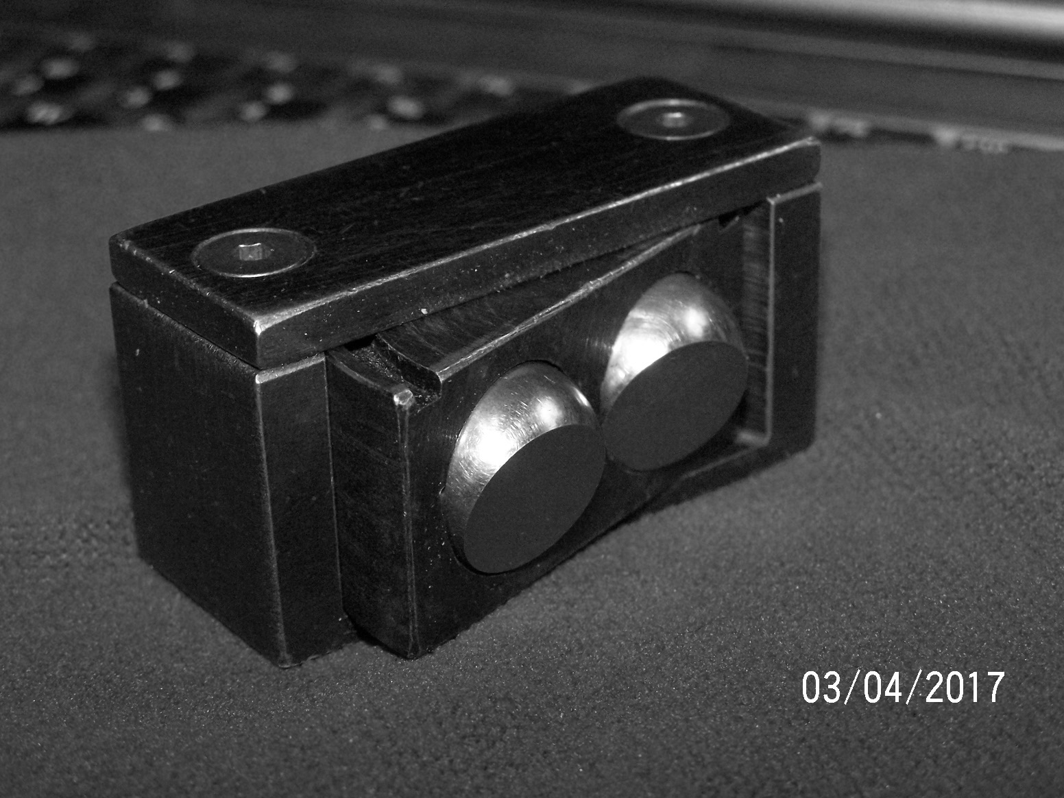
Here's another using a swivel action, for tapers, curves and compound surfaces, as in cast or forged parts. Self adjusting, it uses less space, advantageous when a vise is used.
This is a lathe or mill project, or combination of the two. A little planning will allow making two at a time. Test fits while work proceeds. Heat treating is not needed, or recommended.
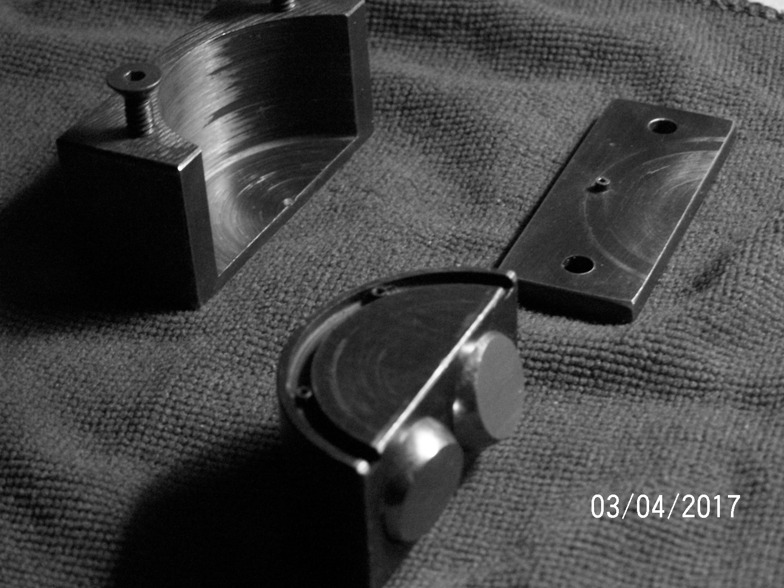
The physical size isn't critical, use steel an adjust to suit material available. Procure two bearing balls, example uses .75/ 19mm. This block is about 2 1/2" long, 1 5/16" high, and 1" deep. The radius inside block [not through] and chord is 1". Allow .002-.004 clearance on one side. The chord has two pockets bored to slip fit the bearing balls. Ball end milling can be used, but isn't required. If pocket is ball-milled, pilot drill around 1/4 ball diameter and somewhat beyond 1/2 ball diameter. Seat depth is .020-.030 deeper than 1/2 the ball diameter. Before assembly, grind flats with any manner at your disposal. Lightly stake the balls in place to be retained, not locked. Top edge of chord is grooved for a roll pin pressed into the top plate. In the groove are 2 roll pins at 45* to keep the chord from swiveling out of the block..
Top plate is countersunk for 2 #10 flat head screws, tapped in block.
jjr2001's post has a similar aspect, and some good building techniques. http://www.homemadetools.net/forum/w...se-balls-50698
This works in vises, hold-downs and a variety of fixturing.
If any amplification is needed, feel free to post or email questions.
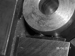
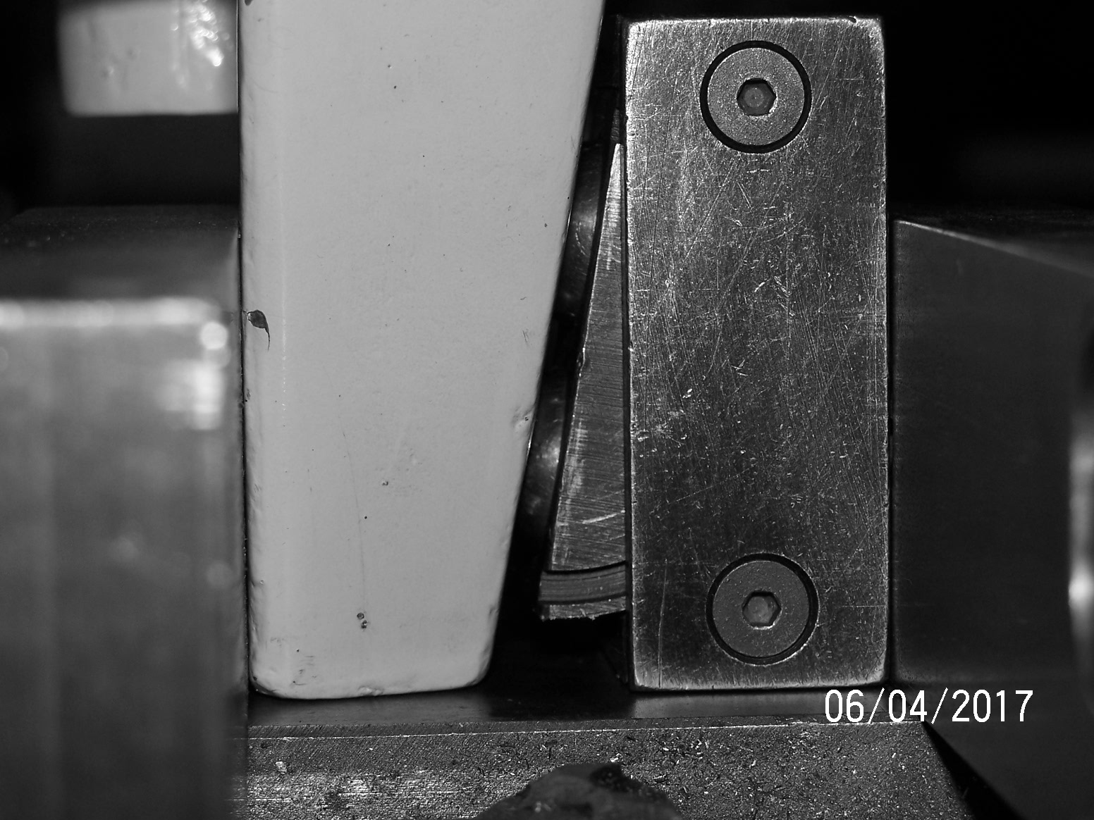
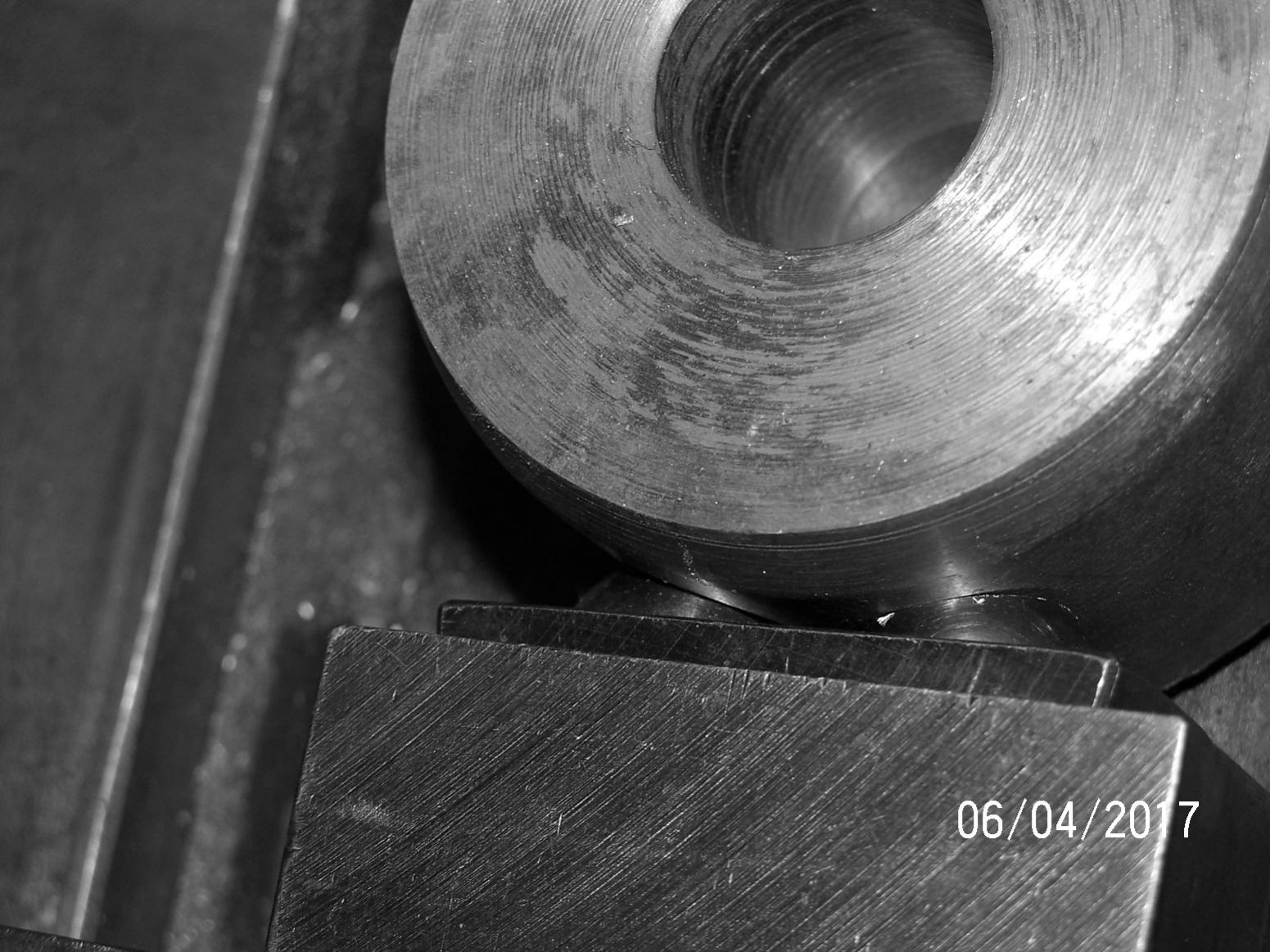
And for Ralphxyz here are 2 shots, to represent use. Only have one suitable casting at the moment,and about a 5" stub of round stock. Casting's the 'apron' from a manual form bender being modified. Round is just a drop from our saw.


 Reply With Quote

Bookmarks