
 LinkBack URL
 About LinkBacks


My tractor has been having starting problems. The only way to start was to hitch the 60a charger to the battery, wait for the voltage to climb over 15v, and crank. If I ever shut off the motor, it wouldn't restart - so a walk (sometimes long) to my truck and get the generator and charger - not so much fun.
In the coarse of over voltaging the system, I managed to break the regulator. So, new regulator, rebuilt alternator, and rebuilt starter and still it wouldn't start. The only clue I had was the starter rebuild guy said it looked like I didn't have enough voltage to the starter. So, I ohmed the cables and they were very solid and to the limit of what I could measure (a few milli-ohms). Still no joy.
Now I checked the voltage to the solenoid from the key switch and sure enough, the voltage was about 1.5 volt less than the battery even with the starter not engaged. Hmmmm... there is nothing in the circuit that would drop that. So, perhaps the wiring from the key switch isn't able to supply the voltage to the solenoid. Might need to replace the key switch, but after replacing the regulator, I learned that parts are becoming unobtainium the more time goes on, so it is time for a different solution.
What if I were to connect the solenoid input directly to the battery? Well, over a dozen cranks later and not one failed crank, we have a winner.
So what to do? Bypass the key switch so that the key switch doesn't need to supply the current to the starter solenoid. Obviously, my test of the direct connection of the input to the battery showed that. A relay was needed. The key switch would close the relay and the relay would energize the starter solenoid. The relay I found was rated at 30a - well more than what the solenoid needed, and it had a 30a fuse and a socket with wires. The relay control was to be the solenoid energize voltage from the key and the power to engage the solenoid would come from the battery, which was connected to the starter with a nice big cable.
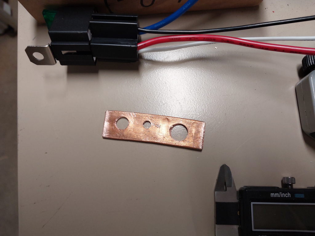
First to make a buss bar to hold/connect everything. This was from a 2.5" piece of 1/2" copper tube. A hammer to flatten (both sides to make it flat) and then drilled for three holes (use step drills after the ppilot hole because copper is soft and grabby) - M10 for the starter battery stud, #10 for the power supply to the relay, and an M6 for the tab of the relay to hold it in place.
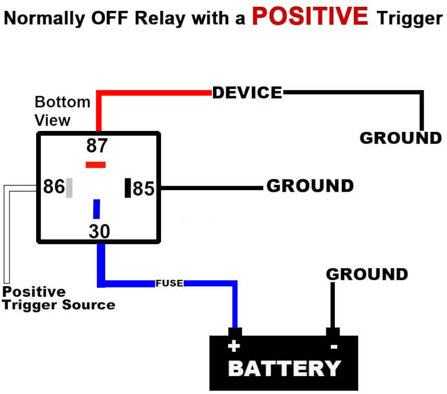
Here is the relay schematic - corrected for the color coded wires of the relay socket:
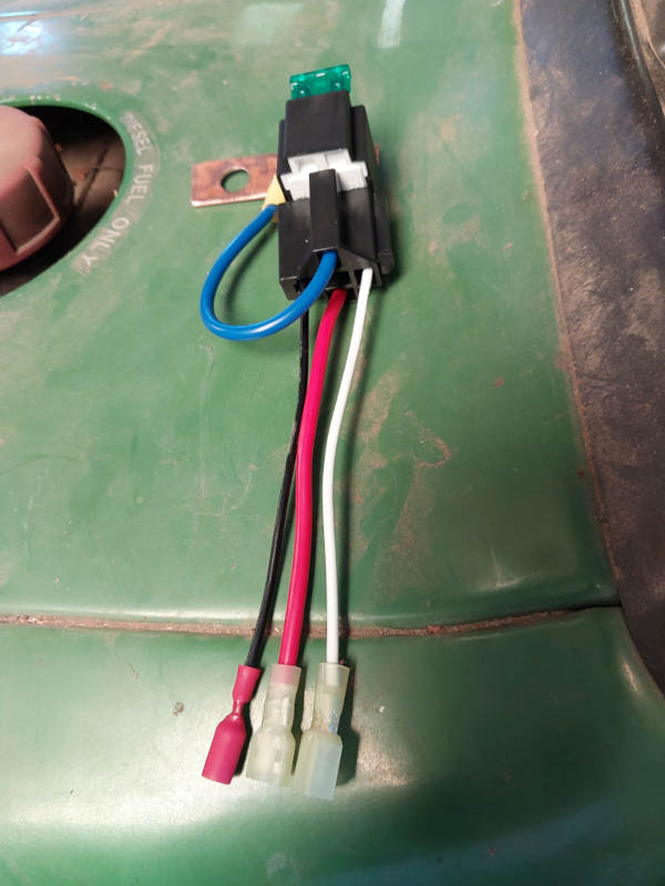
The assembled device looks like this:
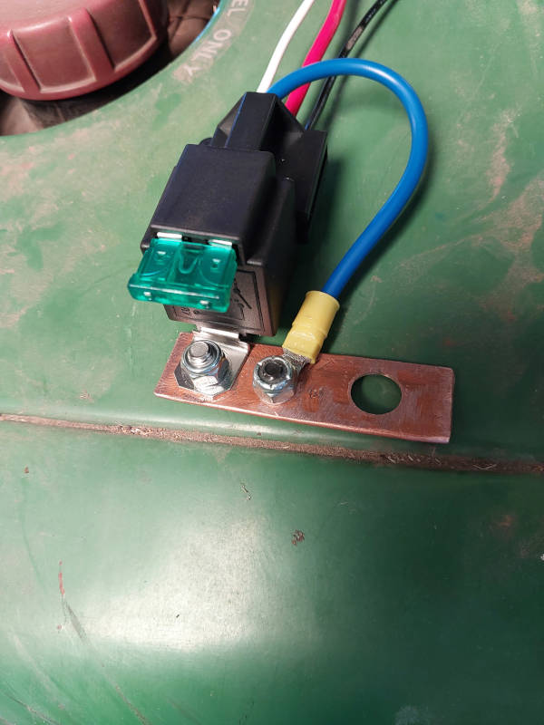
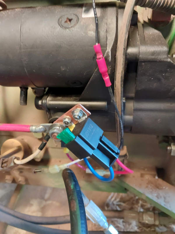
And this is what it looks like installed:
You may need to control a device that needs more power than your switch can handle. If you do, this is how you do it.


 Reply With Quote

Bookmarks