
 LinkBack URL
 About LinkBacks


************ To continue
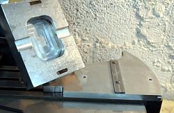
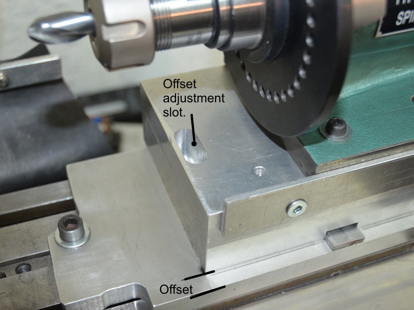
I hadn’t considered a wheel cover originally and when fitted it prevented lifting the table and spindexer to the required height. As shown above this was solved by lifting the spindexer with the aid of an aluminium block. The block came out of the scrap box and was thicker than strictly necessary at 45mm. I could have milled it thinner but there was no disadvantage with leaving it thick. The addition of this block allowed me add the ability to offset the spindexer laterally (Y axis). I have already described the necessity of aligning the spindexer axis directly above the pivot axis of the mounting plate for ball end cutters. However, that is no good for doing cutters which just have rounded edges rather than being full ball nosed. To grind rounded edge cutters the tool bit has to be offset laterally such that the centre of curvature is aligned vertically with the pivot axis.
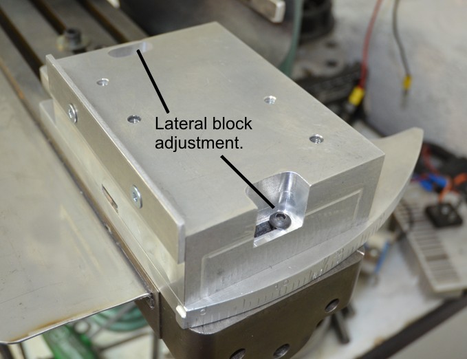
The following photos show details of the block and the slide and groove used to maintain alignment. The pocket in the base of the block is just a legacy of the block’s previous life.
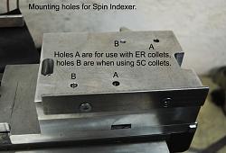
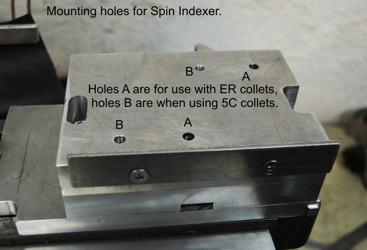
The above show details of the block lateral fixing method. Note also the two pairs of mounting holes for the spindexer. The forward pair are for use when using 5C collets for tool holding and the rearward pair are when the ER25 collets are used. The side fence on the front of the block is for easy alignment of the spindexer when moved fore and aft.
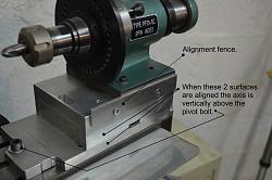

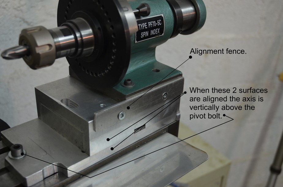
These show the assembled spindexer and mounting block etc. The relevant parts and adjustments are annotated.
Results
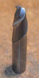

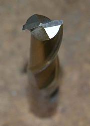
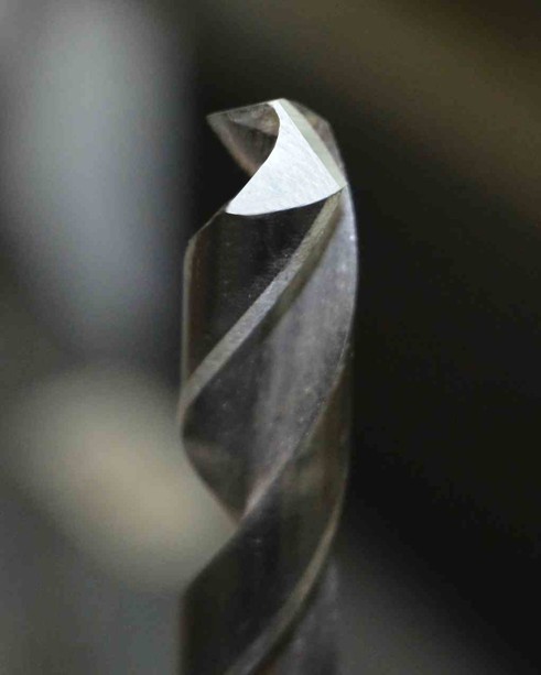
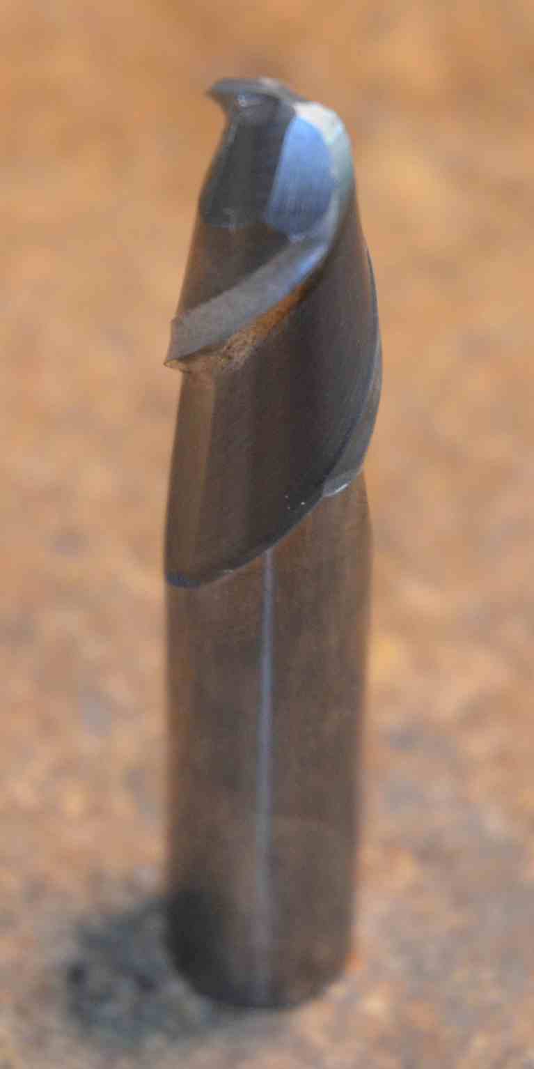
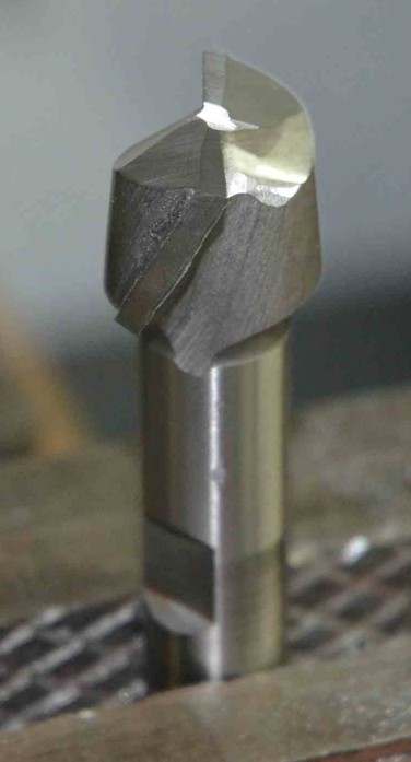
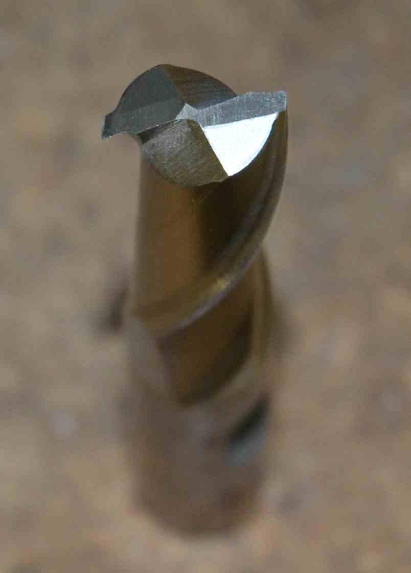
Here are some examples of tools sharpened as test items during the rapid evolution of this T&C grinder.
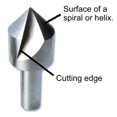
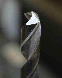
Demonstrating how a multi-toothed countersink bit is ground. Unfortunately, a single flute version such as the one to the right is not so easy. The smooth surface back away from the cutting edge is not a true cone shape but is a section of a spiral or helix. A cone would not cut properly, the bit would just rub. Therefore it becomes necessary to advance the bit into the grinding wheel as it is rotated. There are different ways to do this but with a spindexer the most obvious way is by means of a face cam. I have not implemented that yet and it will probably wait until I have a bunch of those to refresh. In any case as long as the spiral/cone surface is not damaged these bits can be sharpened by grinding on the cutting edge.
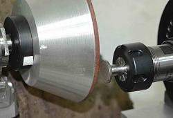
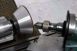
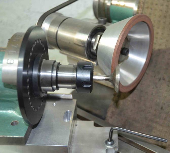
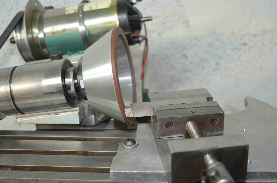
Although built to be a T&C grinder I have found several other uses for it. Two of which shown above. One show it being used to reface a valve. I have a dedicated valve grinder and I had spent some time in the past looking at it with a view to using it as the base for the T&C grinder, but I never found a good way of doing it. Otherwise this post would have been describing that. The other photo shows it facing off a tappet base, It did a great job of that.
More versatility is shown here doing a good job on a HSS lathe tool. Although this method worked well with no problems I later bought a ½” square 5C collet which is more in keeping with its use for other tools and makes setting angles much easier.
A video of the square collet used with a lathe tool is at
https://motochassis.com/FileDump/Tan.../LatheTool.MOV
Conclusion.
One test of how well you have done something is to ask, at the end of some period of use, “With hindsight what would I have done differently?”. In the case of the T&C grinder there is only one thing. If I was doing it again I would mount the grinding head such that I could rotate it about a horizontal Y-axis. I have ended up with just two possible positions depending whether I have the wedge spacer inserted or not. In practice that works fine and only needs to be changed for rounded end cutters, but a head that rotated would be the icing on the cake. That could always be retro-fitted if the mood takes me.
In general it was an interesting project which didn’t take long to make due largely to using what I had and I don’t have a blunt tool in the shop. Drill bits below around 2mm are still done in a Drill Doctor and milling cutters below 3mm just get replaced with new.
Any tool like a mill or mill-drill could be used as a base for a similar machine, Turntable in his “Homemade surface grinder” posting showed us a rigid method of mounting a grinding head to a large mill. There are many suitable options for the grinding head, even a small bench grinder could be used and the Spindexers can be bought off eBay for $40 or so.
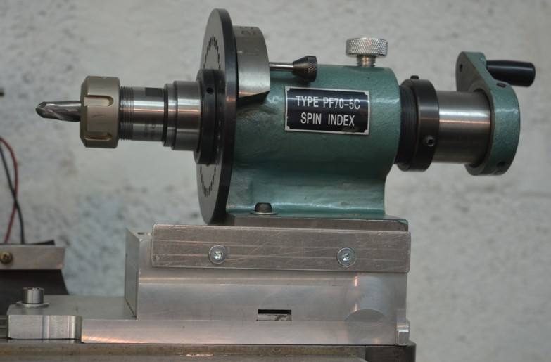
Appendix 1– modifications to the spindexer
In common with many tools from the east, I regarded the spindexer as a kit of assembled parts which needed finishing.
My first task was to dismantle spindexer and machine all surfaces, the base and side/end edges, true to the spindle bore. The bore itself was pretty good and parallel as far as I could measure it. I made a mandrel that fitted the bore and used that as the reference for the other machining operations. I can now trust the alignment of the device.
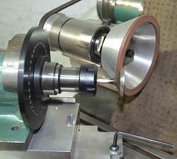
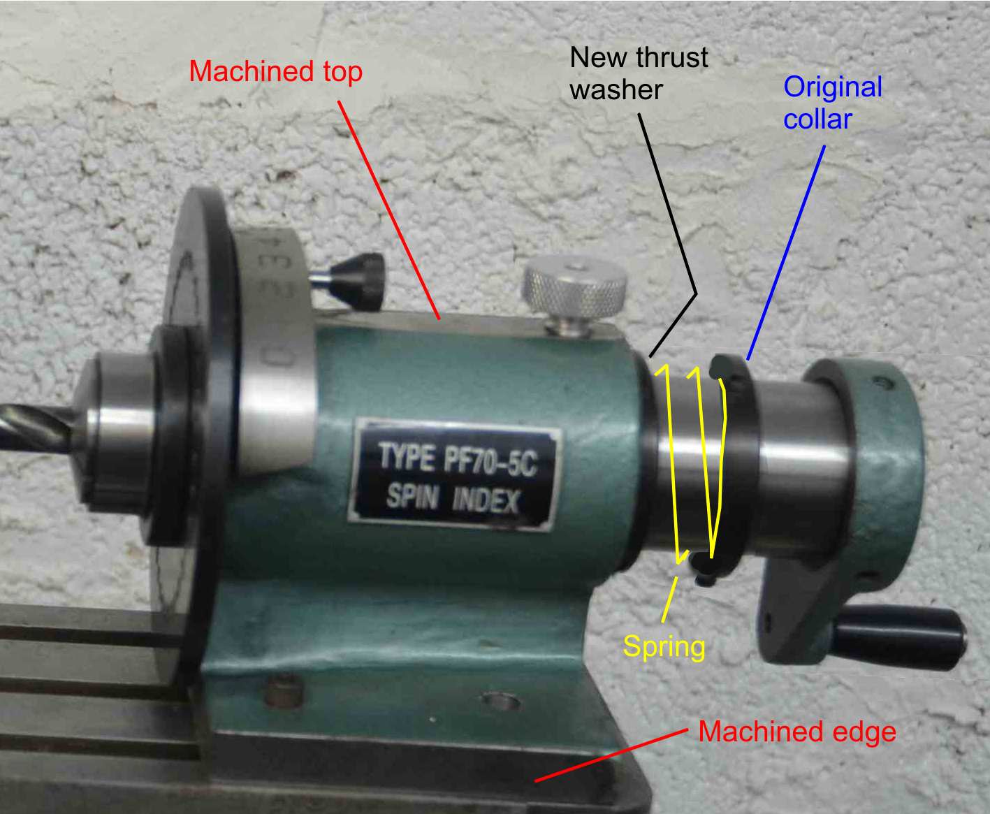
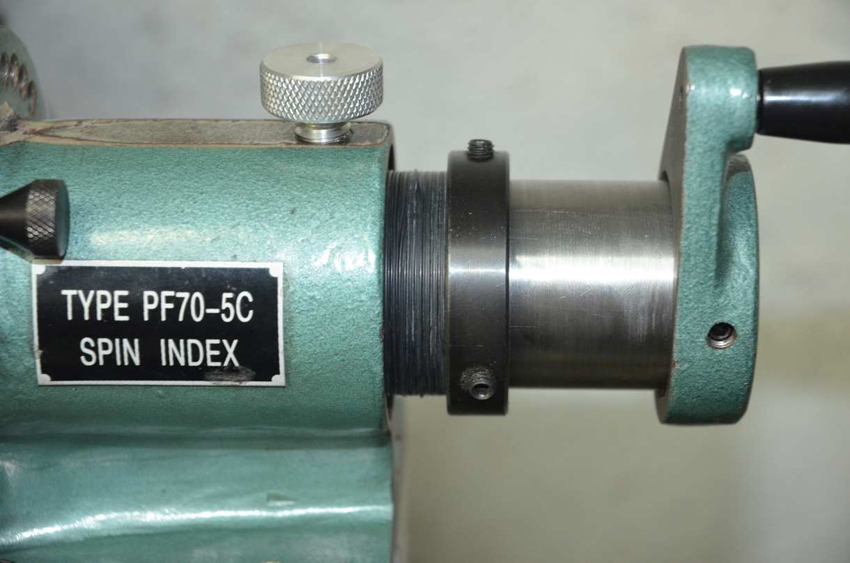
The second thing that needed attention was the method of end float control of the rotating hollow shaft. The stock system is a collar on the rear of the shaft which is held in place by 3 grub screws. It was next to impossible to set this to zero end float without making it stiff and notchy to rotate. End float can affect the depth of the grinding cut and so it is important to remove it to achieve equal height cutting edges on multi-flute tools. The following shows how I proposed a spring loaded collar system to take care of the end float.
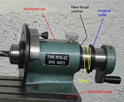
As it turned out I couldn’t find a suitable sized spring but I did have a bunch of X section O-rings, so I packed a few of those on the shaft in place of the proposed spring and said goodbye to end float problems. The following shows the actual solution with the stack of O-rings in front of the original collar.
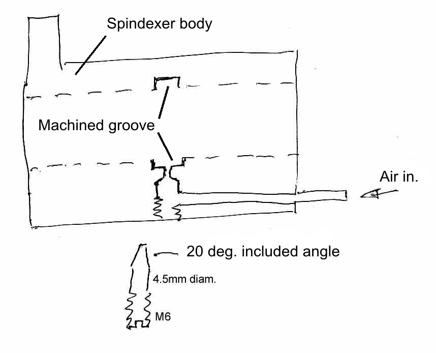
The final modification is to help with grinding the flutes of end mills and reamers. So far the examples shown for grinding tools have focussed on the end cutting edges but side cutting milling tools, drill bits and reamers also get worn on the flutes. Drill bits, mostly have their flute wear near the cutting end and we also rely on drill bits being a given diameter. So often it is better to simply cut off the end part and regrind only the tip. Reamers also are important to be a specified size but they tend to wear over a lot of their length so the only real reclaiming option is to grind the reamer down to the next useful diameter. Milling cutters, on the other hand, are still useful even when ground a little undersize. In order to cut helical flutes it is necessary to move the bit being sharpened along its axis at the same time as rotating it. To allow axial motion with the spindexer it is only necessary to remove the end float collar (and O-rings in my case). The shaft can be moved radially and axially. A stop is used on one flute to maintain the correct helix angle as the tool is fed along the grinding wheel. To achieve a smooth and accurate action whilst doing this double movement, it is necessary to have as friction free and smooth action as possible. The stock spindexer motion wasn’t bad but I thought that it could be improved by making the spindle float on air – turn it into an air bearing. To this end I machined a groove around the inside of the spindexer bore and drilled some holes to feed it with air as shown in this sketch.
I have designed flat surface air bearing before and so I knew a tad about the requirements. To get a successful efficient air bearing it is not just sufficient to feed air to a groove, at some pressures it might seem to work OK until loaded. It is necessary to feed the air in through a restriction fed from a reservoir. Larger feed pipes are usually sufficient for this. In order to have some setup tuning capability I made an adjustable restrictor as shown above. I put Loctite on the threads, and adjusted the screw for the best action and let the Loctite set.
Without the air feed the shaft will rotate between a half and a full revolution when spun by hand, with the air bearing working it will spin for several turns and the whole action is much smoother. Air consumption is minimal and with fading hearing I can’t hear the air exiting, but my dogs can. The air bearing is only used when doing flutes, it is not necessary for normal point sharpening.
Appendix 2 – Explanation of single angle setting
I had a hard time believing how complex the usual multi-axis T&C grinders were. It was the idea of cutting down on the number of independent axes to making just two that appealed to me. Just as if you want to move on an X,Y plane from 0,0 to 10,25 you can do it the long way and move to 10, 0 and then 10, 25 or the easy way in a single shorter diagonal move direct to 10, 25. You can do the same with angles. A simple calculation results in a single angle between the drill bit and the face of the wheel.
Imagine a plain flat rest set at 90deg to the face (side) of the wheel, then lay the drill bit on that with the cutting edge horizontal and the drill angled on the rest such that the whole cutting edge is touching the wheel. If you ground the bit like that you'd get zero clearance angle, but now rotate the bit about its own axis. Now you have a non zero clearance angle but the outside edge will have pulled away from the wheel, now angle the bit a little until all the cutting edge is touching. In that position you only have to plunge the bit into the wheel to grind the first facet of a 4 facet bit. Twist the bit some more and re-angle it and you can grind the next facet with more clearance.
So instead of a relatively complex sharpener all you need to do to grind a 4 facet bit is to mount your drill in some form of holder which can rest on a horizontal plane normal to the wheel and be angled sideways and with provision to rotate the bit about its own axis. I see a $40 spin indexer fitted with an ER25 collect chuck as the bit holder.
To use, just insert the bit in the chuck, angle and rotate it according to the calculations for the required bit included angle and clearance angle and plunge into the wheel up to a set stop or other means of determining the grinding depth. Or else you could feed the wheel to the work.
Appendix 3 – List of videos
I suggest that they be viewed in the order presented here.
This is the first part explaining the magic of the disappearing axes.
https://motochassis.com/FileDump/Tan...r/TC part1.MOV
next is part 2, which has the stuff that that I forgot in part 1.
https://motochassis.com/FileDump/Tan...r/TC part2.MOV
4 facet drill bit sharpening
https://motochassis.com/FileDump/Tan...rill4facet.MOV
The next video shows how the logic of the 2 axes system can be applied to an end mill.
https://motochassis.com/FileDump/Tan...r/TC part3.MOV
Sharpening a ball end cutter
https://motochassis.com/FileDump/Tan...er/BallEnd.MOV
Finally, we see how it also can be applied to a lathe tool.
https://motochassis.com/FileDump/Tan.../LatheTool.MOV
See Appendix 2 for a more complete verbal explanation of the 4 facet sharpening..


 Reply With Quote

Bookmarks