
 LinkBack URL
 About LinkBacks


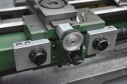
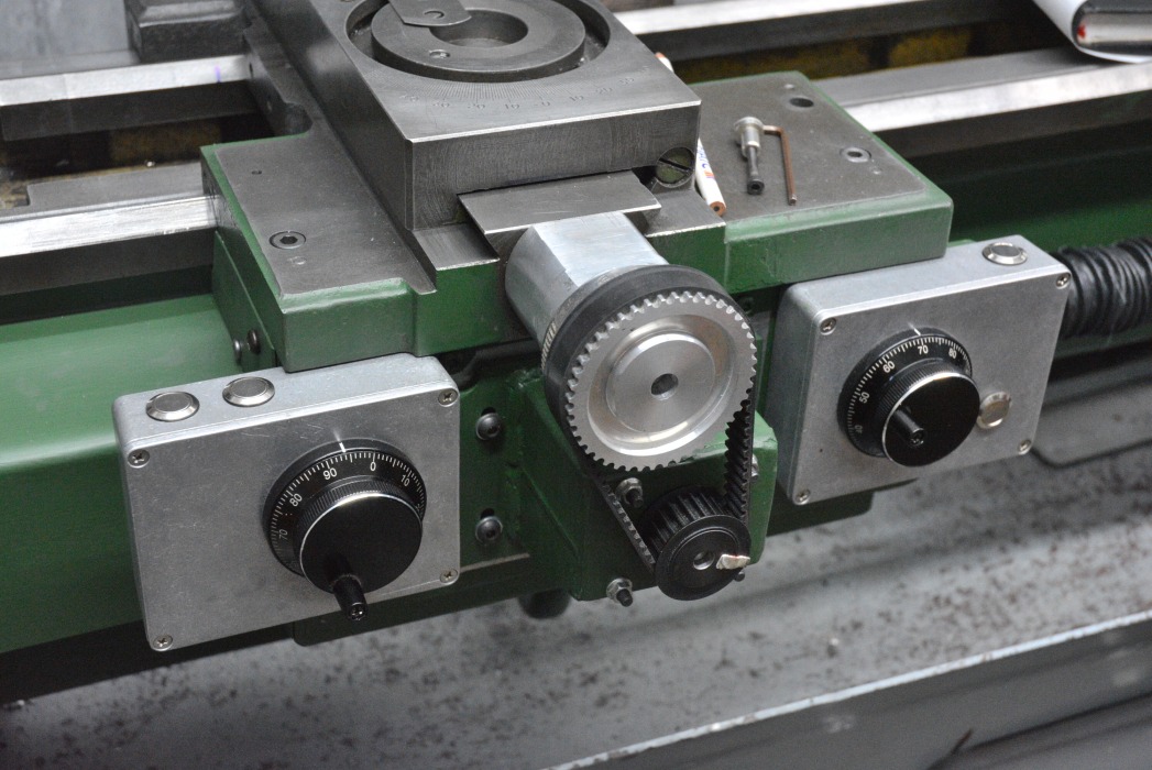
A bit over a year ago I posted about my lathe conversion to electronic control. Not full CNC because I did not want that but way more than normal ELS conversions. Here is a link to that post
Ball screw and electronic lathe conversion
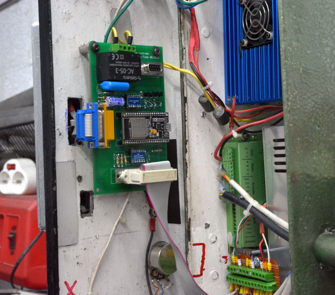
It has worked great since then until it didn't a few weeks back. I traced the problem to a dry joint on my hand wired control board. It looked perfect, even under a microscope, which is about the only way to inspect it. A continuity meter can only tell you if it is working or not at the time of measurement but it may not be tomorrow. Often just putting a probe on a joint can be enough physical effort to change its state. It seems like the modern solder is to blame, it does not tin out like the old leaded stuff. I think that what happened with mine was brought on by the weather. It was very damp over the winter, which would have allowed humidity into anything that was not perfect and caused some corrosion then the hot weather dried it all out. As a result I lost confidence in that board, how many more connections were waiting to cause a problem?. A PCB comes ready tinned on all the connection points and most component leads are tinned or tin easily. Soldering is a piece of cake, with minimal worries about dry joints. So the potential for similar problems is greatly reduced.

Click for full size
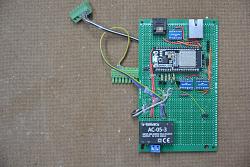
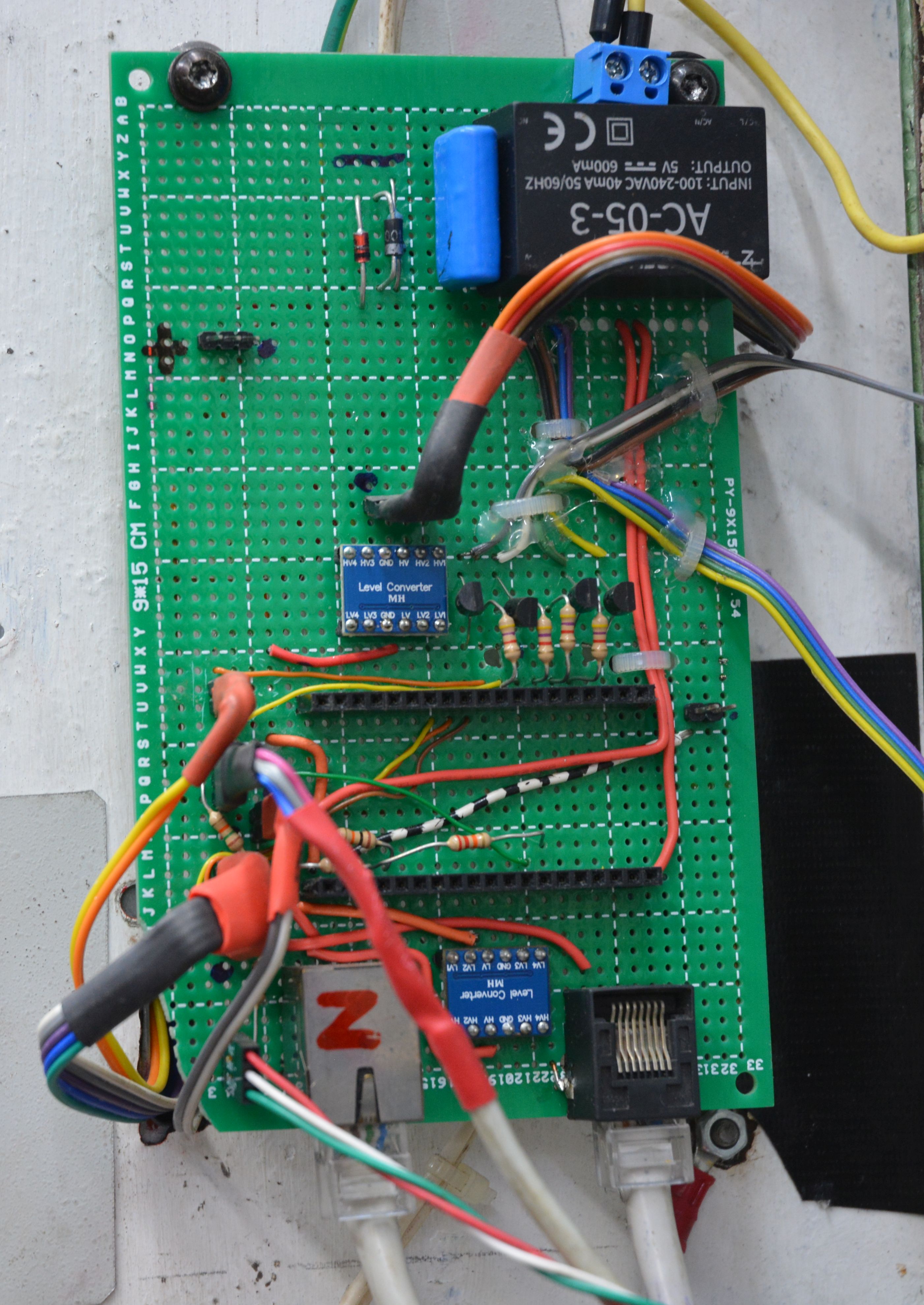
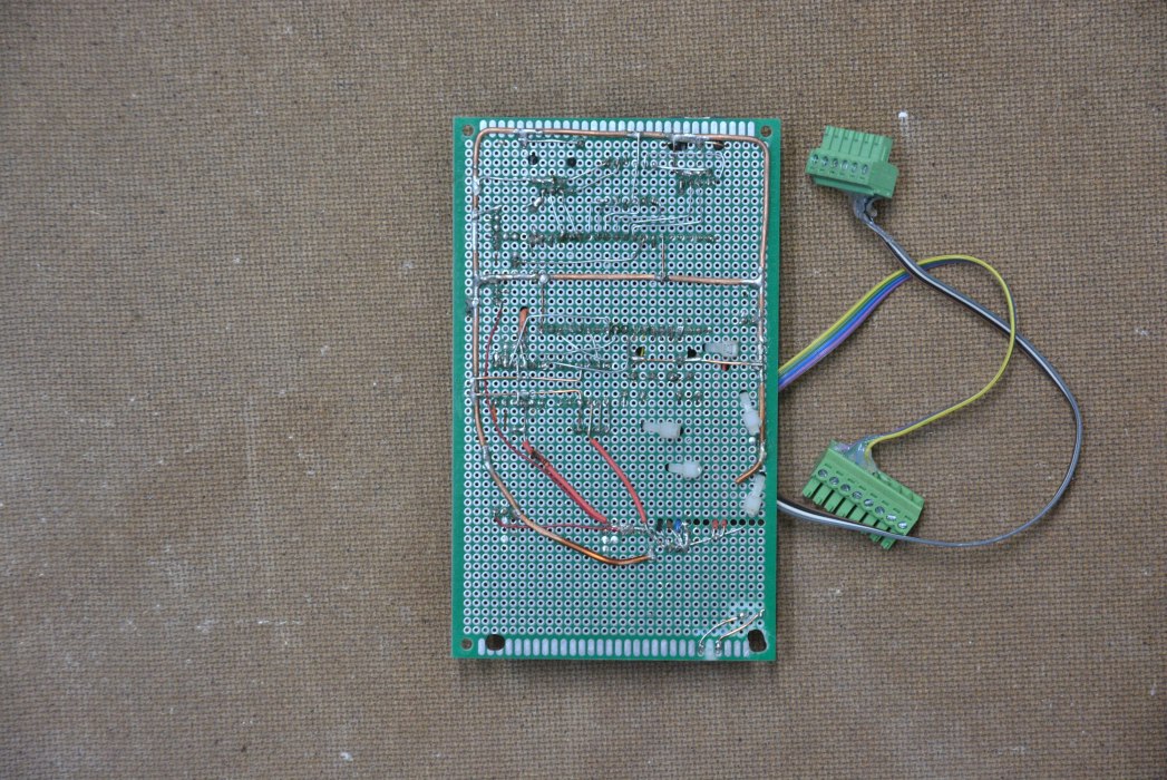
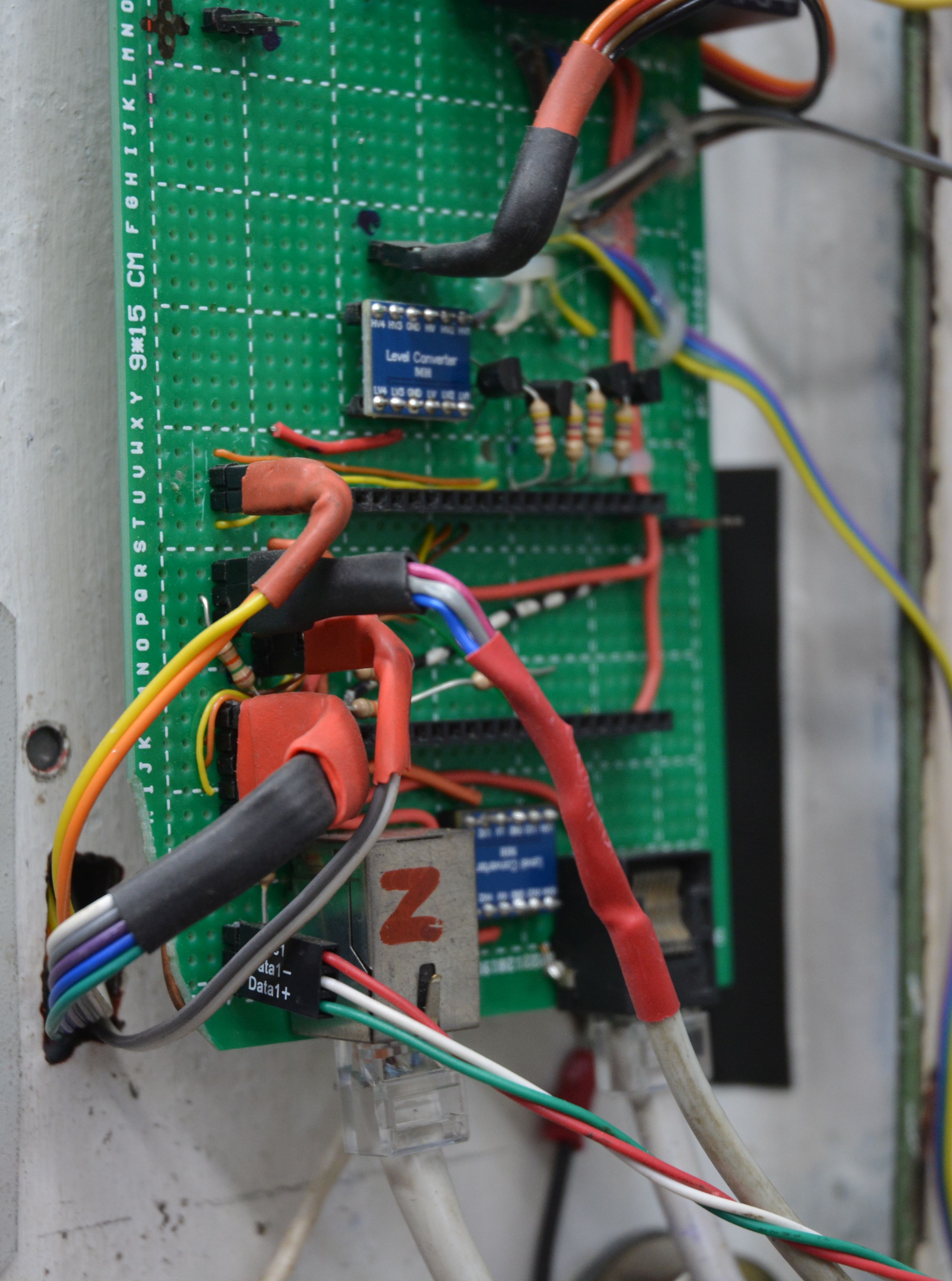
These pix show the original hand wired control board, not tidy but it worked for a year.
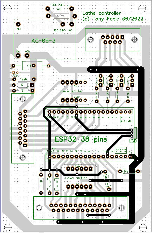
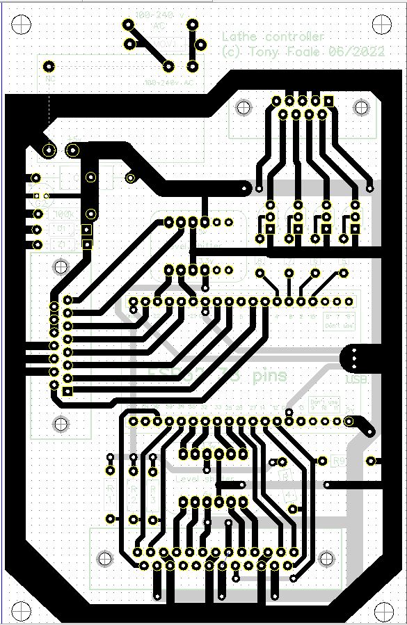
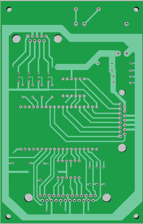
So I sat down and designed a PCB to replace the hand wired board. I have made PCBs in the past on a milling machine but there were a few other people who would like a PCB to help copying my controller, so I decided to design one to get made professionally by one of the myriad of companies offering that service. I used some design software called Diptrace to help design the board. I had not drawn any schematics for the original, I tend to work off the top of my head mostly, so I went directly into manually placing components and then tracing through with the wiring. Here are the front and rear design layouts. Which become the only wiring diagrams that I have.
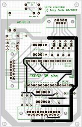
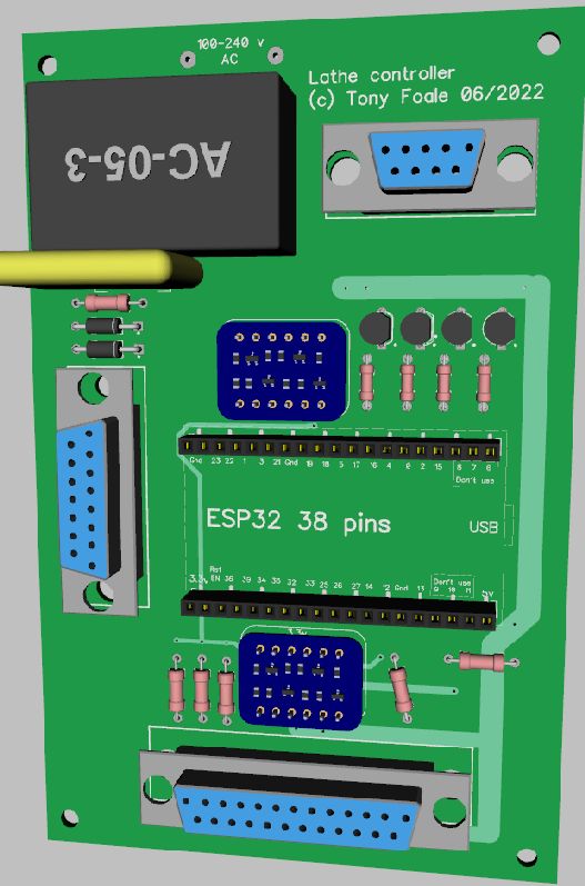
Once that was done I converted it to a 3D image for a final check

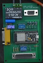
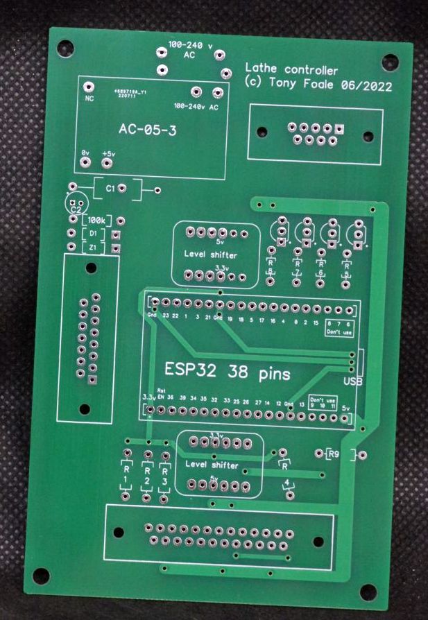
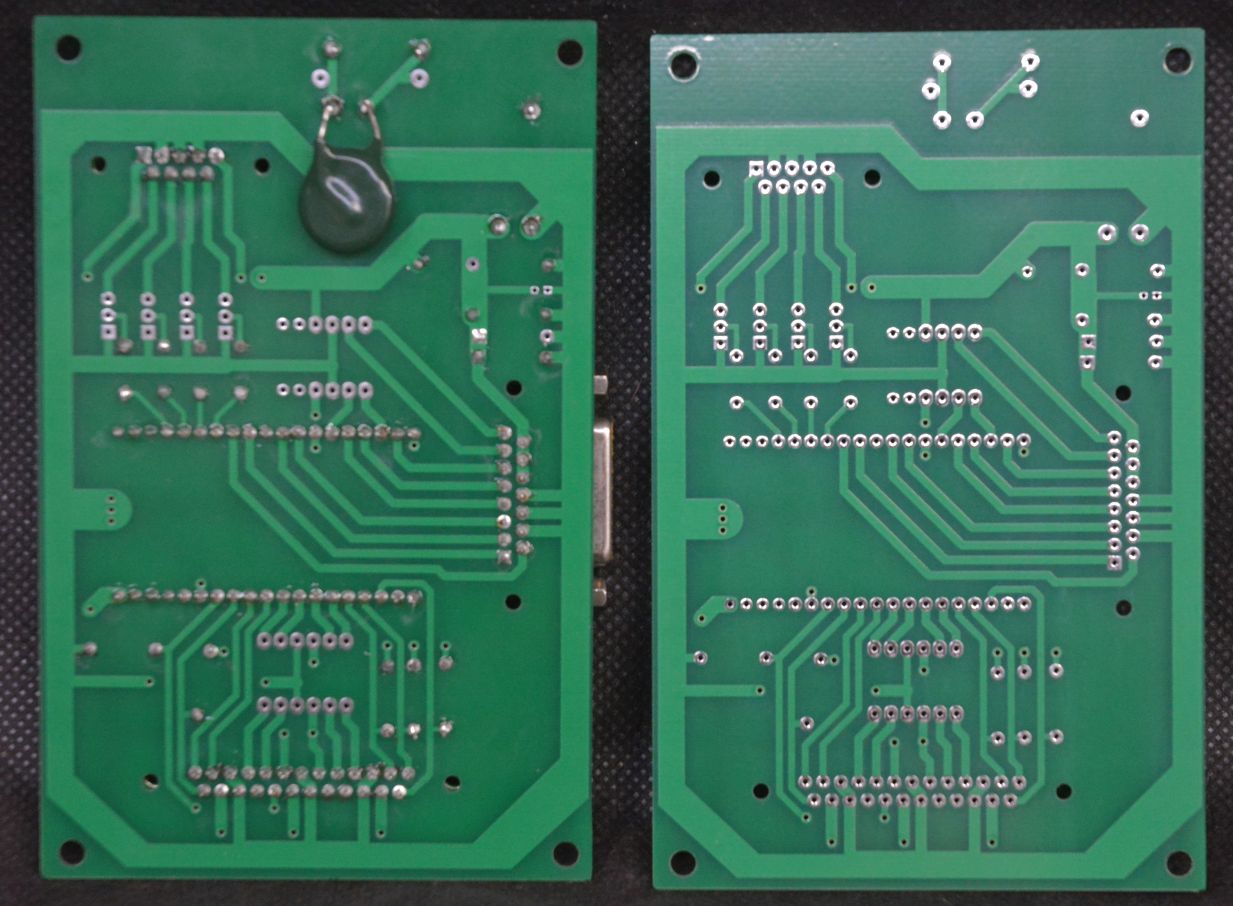
DipTrace then exported a bunch of "Gerber" files that the PCB companies use and I sent them off to such a company. Four days later I had these, The shipping was 8 times the price of 10 boards.

Which were a pretty good imitation of the 3D model
Populating the board with components was very fast and the final board looked like this with the original for comparison.
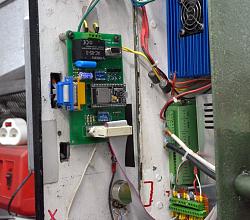
It worked first time but it works no better than the original so what have I gained? Improved reliability and a warm fuzzy feeling whenever I open the cabinet door.
Here is a link to the inevitable videos https://www.youtube.com/playlist?lis...JVwwFANxyTc2Kj and another pic.


 Reply With Quote

Bookmarks