 LinkBack URL
 About LinkBacks
Is this for single to three phase ???
Dave
Originally Posted by nhengineer


Is this for single to three phase ???
Dave


$700 US FOB Anaheim, CA, USA and you'd need to fabricate your own enclosure.
How are using this transformer
I was thinking this for single to three phase
Most motors that are 415 volt can also be wire 240 they wye/delta wound motors
I think take close look at the motor to see what type it is most wye delta motor are 6 wire type
Dave
 by old kodger - Rhengieer,
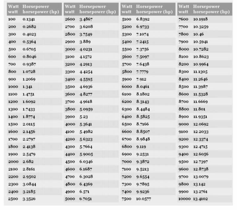
I thank you for your effort, but now you see what I mean when I say, in Australia most of the options to date are totally uneconomic, for instance, I need to power a 3 phase mig welder which is name-plated at 10 amps per phase which is about 7.1kw at 230 volts. If a 3hp transformer is likely to cost $450 US that's around $600 AU, and I might need two...$1200 plus freight, and as I mentioned befor "Pin It")
Rhengieer,
I thank you for your effort, but now you see what I mean when I say, in Australia most of the options to date are totally uneconomic, for instance, I need to power a 3 phase mig welder which is name-plated at 10 amps per phase which is about 7.1kw at 230 volts. If a 3hp transformer is likely to cost $450 US that's around $600 AU, and I might need two...$1200 plus freight, and as I mentioned before freight from the US to AU needs the surrender of ones first born, I would not be surprised to find that the freight exceeded the initial cost of the transformers. Also 3hp would woefully inadequate, I need at least 10 amps per phase, for a overload margin, maybe more.
So at a potential cost in excess of $2400, a second hand 3 phase generator is starting to look a lot more realistic.
I thank you for all your effort, and indeed to all the other contributors to this thread, but unless I can find a way to control a synchronous motor acting as a generator, I have two options:- buy a generator or attempt to rewire the welder to run on single phase. Incidentally, I'm informed by the manufacturers of the welder, that the configuration internally is actually three separate transformers feeding a bank of full wave bridges, so it could be possible.
If anyone is interested I'll keep you informed.
Rob.
That will work for your
Good luck
Dave


Not knowing which machine you have so I cannot tell you that yes it is possible however most of the older 3 transformer machines can actually be re wired to run on single phase the issue in your case may be having the only 1 hot single phase type current. THat being said you might crawl down this rabbit hole and have a go at a rather long thread where some guys have converted some 3 ph mig welders to run on single phase
Miller CP-250TS converted to single-phase
Never try to tell me it can't be done
When I have to paint I use KBS products
Like your thinking Frank low cost too
The only item on welder is in some cases the cooling is 3-phase still low cost to change with off the shelf fan. I do not see a fan on the Miller CP-250TS
In worst case it no change it would only be 2/3 the amperage.
Dave
Last edited by smithdoor; Jan 19, 2017 at 09:37 PM.

Make up a number to give them.
Smithdoor, and everybody else,
I am fully, completely, and absolutely aware that the power supplied to most households in the US, including mine, is universally called SINGLE PHASE or split phase. And I am aware of WHY this terminology is used. There really is no reason to try to argue with me about this. As far as common usage is concerned, I do concede that point.
BUT, when most three phase converters use this split phase, "single phase" 230 Volt household source to create three phases to run a motor, they only create ONE additional line. So, they take this three wire, split phase, single phase supply and add only one wire and bingo, they have three phases. And the ground wire from the original split phase supply is NOT one of them. Freaking magic! Add one to one and you get three. WOW! What a concept.
At the output of the phase converter you have three phases: split phase #1, split phase #2, and the new phase that is generated by the circuitry of the converter. In understanding this feat of magic, that third phase and I don't mean the one generated by the circuitry in the converter, has to come from somewhere. It wasn't really magic, it was one of those original "split" phases. And there were two of them. I, in my scientific brain call that a two phase feed. TWO distinct phases are already present in what the entire electrical power business in the US calls "single phase" or "split phase". They really are there: TWO of them really are there. They really are not in phase with each other so, in reality, they really are TWO distinct phases to begin with.
The real mystery is how can they be 180 degrees out of phase with each other at the supply line coming into the house and then, after passing through the phase converter with nothing but metallic paths inside that converter, they suddenly are only 120 degrees out of phase when they get to the motor you/we are trying to supply with three phase power. Phasing magic! For a long time I believed that the output of a simple phase converter was actually three phases that had a 90-180-90 phase relationship. It took me a while to realize what was actually going on there. But it is real and it does work. And they really are 120 degrees apart at the motor (120-120-120). If you want to argue with my use of terminology, then you explain that FACT. Hint: it helps if you open up your mind to the idea that they really are TWO PHASES in the first place, not just one. I await your explanation.
I have never read a really understandable explanation of this that does not involve many pages of complex math., usually chapters of them. I have made a mental note to try to write a simple and concise explanation that all can understand without integrals or vector math, but I am not sure it can be done. I have a daughter who taught college level physics and I may enlist her help in this. She liked to come up with new ways to make things understandable. I had to work it out with vectors and I had to go over it several times before I was convinced that it was correct.
There have been 10 pages of comments here sometimes it appeared to me that the ultimate solution to an individuals problem was running off of the rails, However the main topic has been to come up with a working plan to have 3 ph power where none is readily available. Then there is the economics side of the situation. " nhengineer" has in my personal opinion been quite diligent in his personal research to this as well. Every time myself or others have opened different avenues of approach he did his own research for the feasibility of our ideas. I believe it requires one to have a very open mind to accept that there are sometimes many problems to 1 solution as well as the counter side many possible solutions to a given problem, and while personally I know that I can construct my own Rotary phase or a static converter from knowledge and experience gained over the years I'm going to purchase a set of his plans even though I do not need them. My view on this is it never hurts to have more information.
Never try to tell me it can't be done
When I have to paint I use KBS products
There are currently 3 users browsing this thread. (0 members and 3 guests)
 Posting Permissions


 Reply With Quote
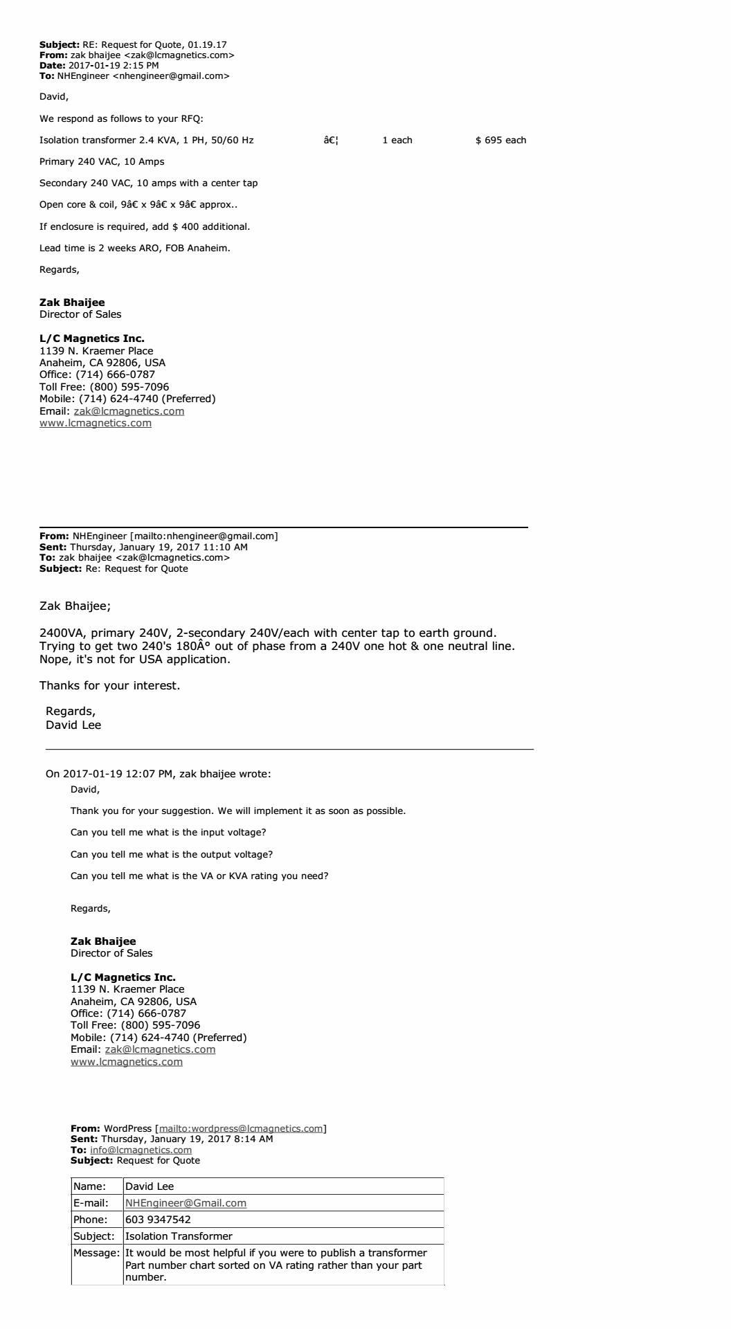
Bookmarks