
 LinkBack URL
 About LinkBacks


My Tool & Cutter grinder.
I have always lusted after a Tool and Cutter (T&C) grinder. I don’t know why, but who can explain love, after all it is just a tool for sharpening blunt drills and milling cutters. Not very exciting, and I’d have more use for a cylindrical or surface grinder. Anyway a few months back I took the bull by the horns and made one which incorporated a few of my ideas for a mechanical simpler machine than the norm but without any sacrifice of functionality.
NOTE: For reasons unknown to me the next three photos refuse to display. I have posted them again in post #4 below.
Attachment 15826
The basics
Three existing items formed the base components of this machine. I had previously built a tool post grinder for my lathe but it was made with a consideration that it might prove useful to be able to attach it to other machines as well. A T&C grinder had been rattling around in the deeper recesses of my mind for quite some time, and the tool post grinder was the final piece of the puzzle.
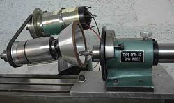
A while back I bought, at a flea market, what appeared to be a quill and spindle from a small mill/drill machine. I knew it would be useful one day and it was cheap as well. The spindle had an internal Morse taper No. 2 which was ideal for the grinding wheel arbours as we’ll see. It was as if it was made for my grinder. To power it I wanted a variable speed motor. Options for that were a small 3 phase motor with a variable frequency drive for control or a DC motor which could be controlled by the applied voltage. I had a 2hp DC motor from an exercise treadmill and I decided to use that. The following picture illustrates how the grinding head was constructed from those parts plus some aluminium from the scrap box.
DC motors have their speed controlled by the applied voltage, for initial testing I simply used a Variac (a variable voltage auto-transformer). Later I made a PWM (Pulse Width Modulation) system for control, I used a double 555 timer chip to provide the variable width timing pulses which were sent to the motor control MOSFET through a gate driver chip for fast switching. Very simple, very few components and which are dirt cheap these days.
Attachment 15827
The grinding head, showing the re-purposed mill/drill quill and spindle on the left and the DC motor salvaged from an exercise machine, on the right. The large hole in the aluminium block is to mount the assembly in place of a lathe tool post. Note the MT2 taper in the spindle.
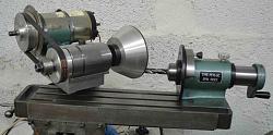
I also had a small horizontal milling machine which I made from scratch in the 1960s. It hadn’t been used for 50 years and looked to be in poor shape but after dismantling and cleaning it came up as new. It was an ideal platform on which to mount the grinding head to make a capable T&C grinding machine. The mill was described on this forum in a prior posting.
Attachment 15828
The small horizontal milling machine which I made around 55 years ago. A good clean and a coat of paint had it back to its former glory. The milling head will be replaced with the tool post grinder head.
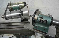
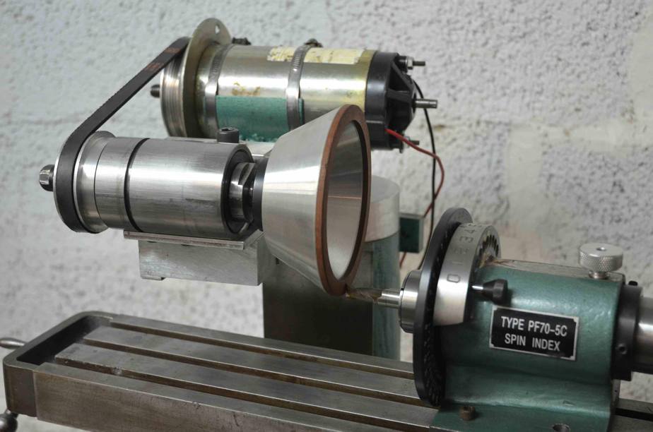
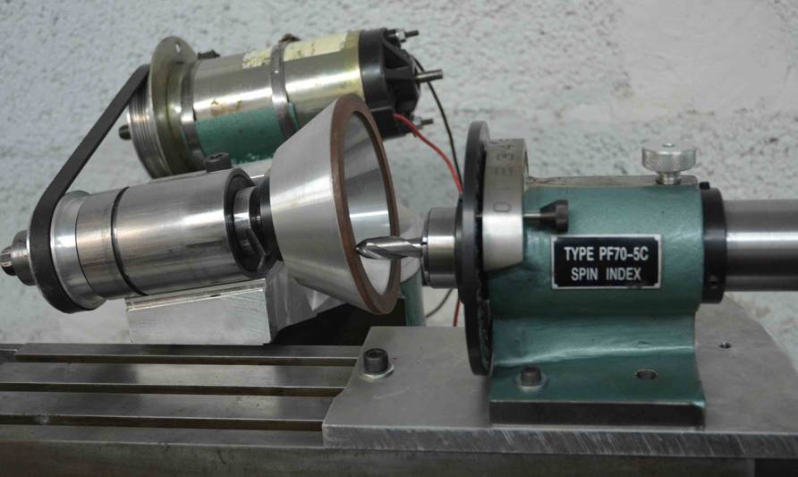
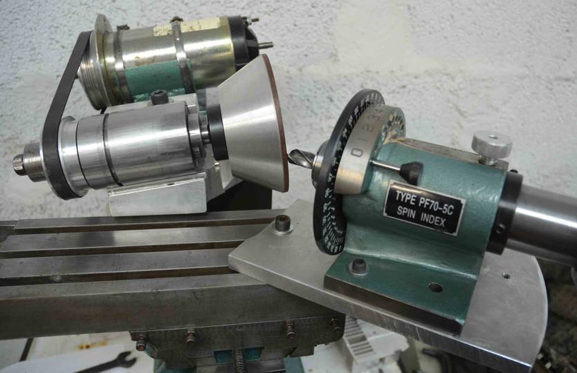
The third item to complete the machine is a what is called a Spin Indexer (or Spindexer). Which is a holding fixture with a vernier adjustment which allows rotary motion in 1 degree increments. It comes with a through hole to take 5C collets. I also have an ER25 chuck with a 5C arbour so overall I am well covered to hold drills and milling cutters from 1mm to 25mm. This indexer will allow drill bits and milling cutters etc. to be rotated about their own axis to present the cutting edges in turn to the grinding surface.
I made some modifications to improve the spindexer which are outlined in Appendix 1, at the end of this document.
An aluminium block is the mounting for the grinding head. It is spigoted to the vertical mill column and can rotate about a Z-axis. The block is offset to the left to reduce the needed overhang of the mill table and indexer. The Spin Indexer is mounted directly to the mill table, this will be changed later.
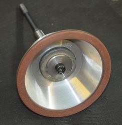
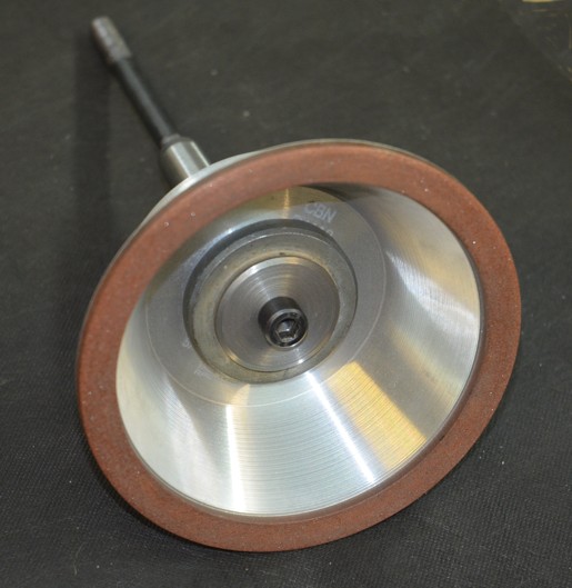
The only items that I didn’t already have were suitable grinding wheels. There are many shapes of wheel available for T&C sharpening but unless you are sharpening tools on a frequent basis it becomes uneconomic to keep a wheel for every type of required cut. I choose to get identical flaring cups, one of CBN and another of diamond. Flaring cups are a good overall compromise and allow most types of cutting. CBN is great for steel tools, it cuts cool and can be used dry or with liquid coolant, it has high metal removal rates and wears very little itself. Diamond is the abrasive of choice for use with tungsten carbide tools, but is unsuitable for steel.
Here are some common wheel shapes used for T&C work.
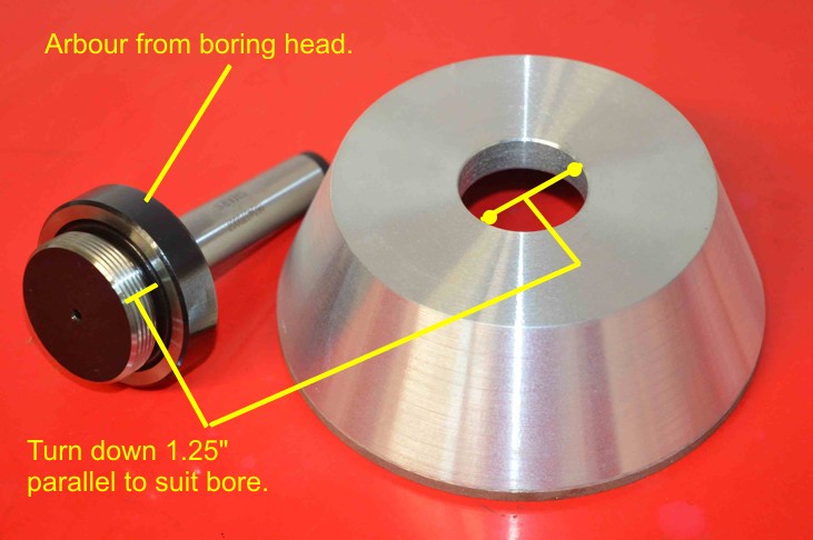
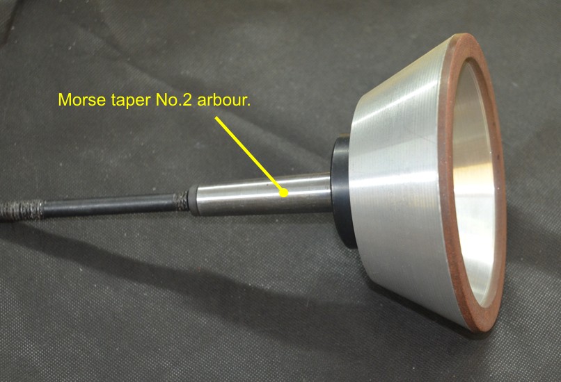
The smaller industrial grinding wheels like these generally have a 1.25” (31.75mm) mounting hole. Rather than remove each wheel from a single arbour when a wheel change is necessary I decided to mount each wheel on its own arbour and then change wheels and arbours together in the interests of accuracy and repeatability. This was the main advantage of using a spindle with a MT2 taper. The easiest and quickest way to get suitable arbours was to use standard arbours made for boring heads, modified by turning the mounting down to 1.25”.
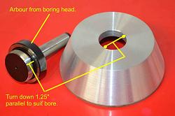
Left shows the threaded arbour for a boring head. The thread was turned off down to a parallel diameter of 1.25” to suit the wheels.The others show the assembled wheel and arbour complete with a draw bar to hold the taper into the grinder spindle.
How others do it
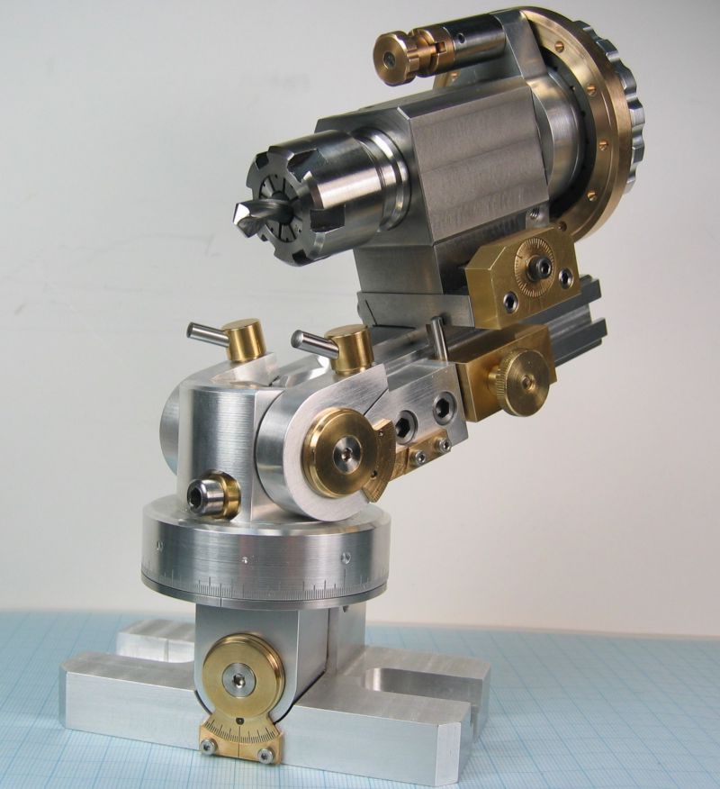
Many (most?) tool and cutter grinders use multi-axis tool holding systems, mostly 3 overall axis plus a spin axis for indexing the tool bit as shown in this beautiful piece of mechanical art below.
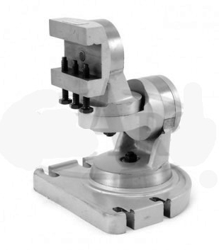
For the lazy, you can buy a 3 axis work holder for less than $100 on eBay, as per the following, and I did consider this option. The top section could easily be machined to take the spindexer to provide the tool indexing function.
Why I do things differently.
However, I am a great lover of simplicity and a little knowledge of 3D geometry led me, a long time ago, to realize that as fascinating as these 4 axis system are, they are totally unnecessary. You can achieve the same results with a single global axis plus the indexing axis, thereby cutting down on fabrication work by a large margin. How is this possible and why doesn’t everyone do it? The first is explained in the following but the second question eludes me, maybe it’s a case of “it has always been done that way”.
Consider the face of a grinding wheel as a flat plane, and as an example let’s think about grinding a drill bit with a 4 facet grind. (For those unfamiliar with 4 facet drill bits, I suggest asking Mr. Google, he has lots of info. on the subject.) We want to present the drill bit to the wheel such that it touches the wheel at the required nose angle and also the required clearance angle. So with the traditional multi-axis machines we would probably use the indexing axis to set the cutting edge either horizontally or vertically depending on the specific machine. Then we would set one global axis to the nose angle and another axis to the clearance angle. Simple and very understandable. However, no matter how many angles the tool bit is moved through in the end the bit’s axis will form a single angle to the plane of the wheel’s face, so we only need a single global axis to present the tool to the wheel at the combined angle of the two movements. Too good to be true? Yes it is, if that that is all that we did then the cutting edge of the bit would be given a clearance angle of zero, we can get around that problem by twisting the bit around its own axis. So now all we need is a single global axis and the indexing or twist axis of the tool. A bit of trigonometry is all that is required to calculate what those angles should be given the nose and clearance angles that we are after, and I made a spreadsheet to do the heavy lifting. This principle can be applied to other types of tools such as end mills and even lathe tools.
I made this T&C grinder a few months ago and by way of explanation to some friends over the net I made a few videos explaining how this angle juggling works. These videos are about 5 mins each. Bear in mind that a few comments were directed at my friends based on prior correspondence, the videos were not scripted beforehand and so parts may not flow smoothly. I suggest that they be viewed in the order presented here.
This is the first part explaining the magic of the disappearing axes.
https://motochassis.com/FileDump/Tan...r/TC part1.MOV
next is part 2, which has the stuff that that I forgot in part 1.
https://motochassis.com/FileDump/Tan...r/TC part2.MOV
4 facet drill bit sharpening
https://motochassis.com/FileDump/Tan...rill4facet.MOV
The next video shows how the logic of the 2 axes system can be applied to an end mill.
https://motochassis.com/FileDump/Tan...r/TC part3.MOV
Sharpening a ball end cutter
https://motochassis.com/FileDump/Tan...er/BallEnd.MOV
Finally, we see how it also can be applied to a lathe tool.
https://motochassis.com/FileDump/Tan.../LatheTool.MOV
See Appendix 2 for a more complete verbal explanation.
The implementation
The construction and manner of use of my T&C grinder evolved over the short period of the few days of its construction. Normally, I tend to think through every aspect of something that I am about to make but in this case I didn’t. I started making it without much prior thought and as a result I had to make a few changes along the way. There were basically 3 iterations.
The first saw the Spindexer bolted directly to the mill table with the grinding head able to rotate about a vertical Z-axis. This allowed the stone to be presented to the tool at appropriate angles to get the rake and clearance angles required. This arrangement enabled the vast majority of bits and cutters to be ground but a notable exception was rounded nose cutters. To grind such tools it is necessary to be able to rotate the tool point itself about a vertical axis. That on its own was insufficient though, as it would be impossible to grind the clearance angle equally around the curved nose.
The next iteration was to solve those problems. The Spindexer was mounted on a plate which could rotate about a vertical pivot bolt and the grinding head was then rotated a fixed amount about a horizontal Y-axis by machining its mounting plate at a 7 degree angle, which is a good compromise 1st clearance angle for many tools. The machine now did a good job of ball ended cutter as well as drill bits, end mills and slot drills but it lost the ability to face off a badly damaged tool flat at 90 deg. to clean it up to start over. It also became less suitable for grinding the flutes of tools.
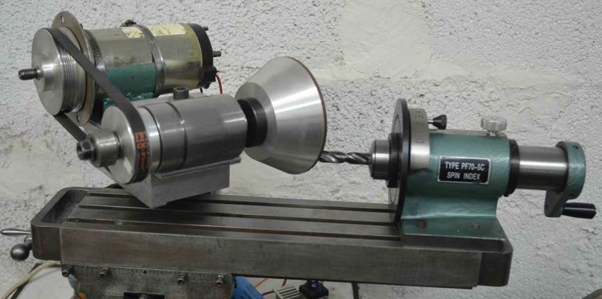
The third and hopefully final iteration had the Spindexer raised up on a block to achieve more clearance under the grinding wheel, when fitted with a cover. The block at 45mm high is taller than necessary but it was the most suitable piece in the scrap box. Another change was the insertion of a removable wedge shaped spacer under the grinding head. This spacer brought the spindle axis back to horizontal, but the simple removal of the spacer allows the return to an angled wheel face permitting the sharpening of rounded nose cutters.
Although the grinding head still has the ability to rotate about the vertical Z-axis, I have yet to encounter a situation where this would help in the 3rd and current iteration.
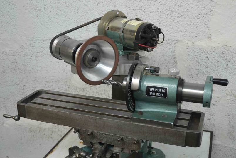
First design iteration. The Spindexer is bolted directly to the mill table and has no angular degrees of freedom other than about the tool axis. On the other hand the grinding head has been rotated about a vertical Z-axis by the value of the required clearance angle on the end mill. This arrangement worked perfectly but was incapable of grinding round nose cutters.
Two possibilities for sharpening a drill bit to the 4 facet specification with the 1st iteration design. Note in the left photo that the mill table and Spindexer are forced into a position with a lot of overhang. This is not a good setup for such a small machine and the other option is preferable and has the added bonus of improved visibility at the cutting edge.

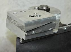
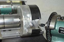
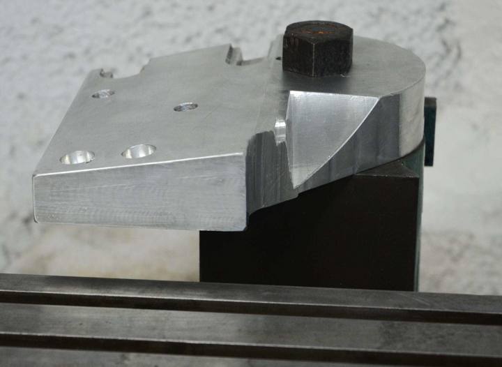
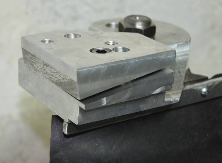
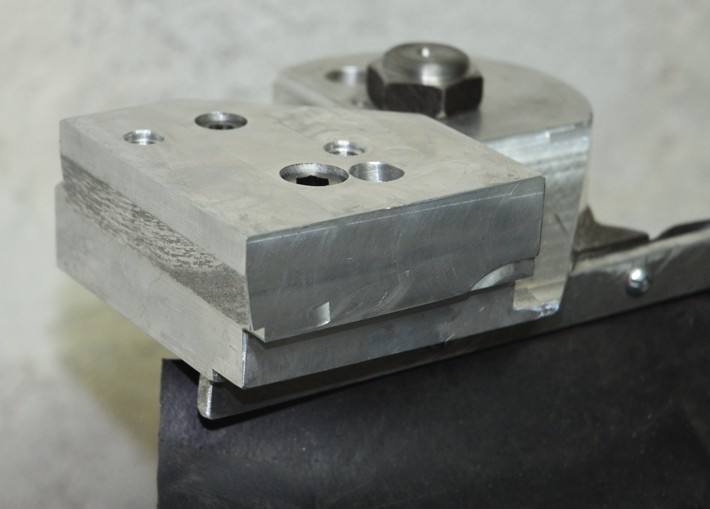
Grinder mounting block after being machined at an angle of 7 deg. So far this has only been used for sharpening radiused cutters. The other pix. show the wedge shaped spacer which, when fitted, returns the wheel face to the vertical.
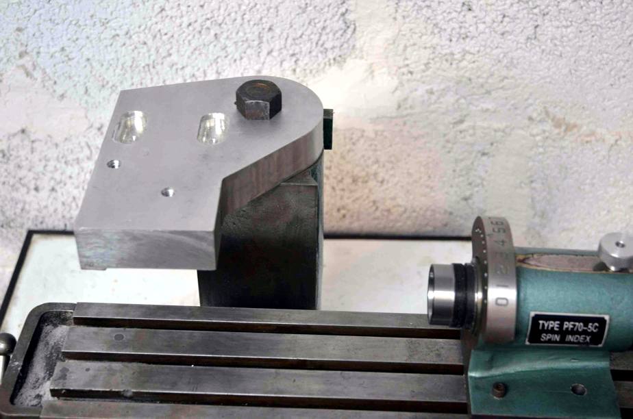
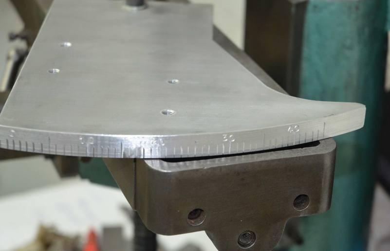
Mounting plate for the spindexer. Pivoted about a vertical axis, just visible at the top of the photo. Graduated 0 to 45 deg.
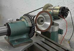
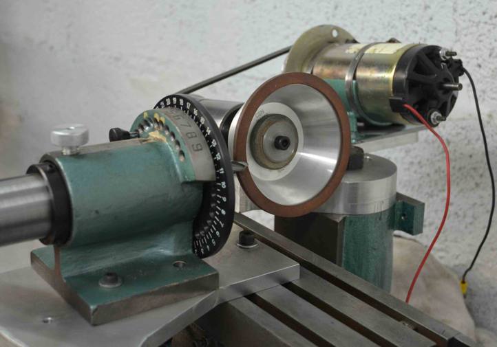
The above 3 photos show the rotation of the spindexer about a vertical axis to grind all the way around the end of a ball ended cutter.
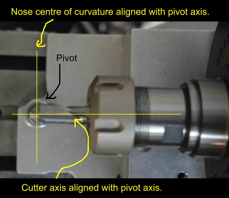
Here we can see how the centre of the radius on the end a ball ended cutter needs to be aligned with the vertical pivot axis of rotation of the mounting plate of the spindexer.

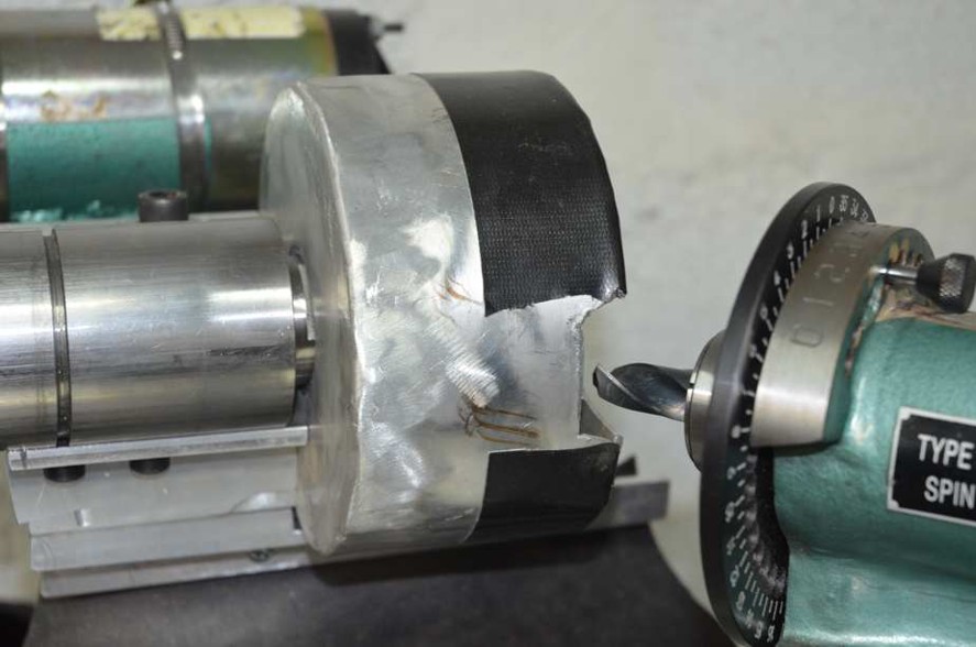
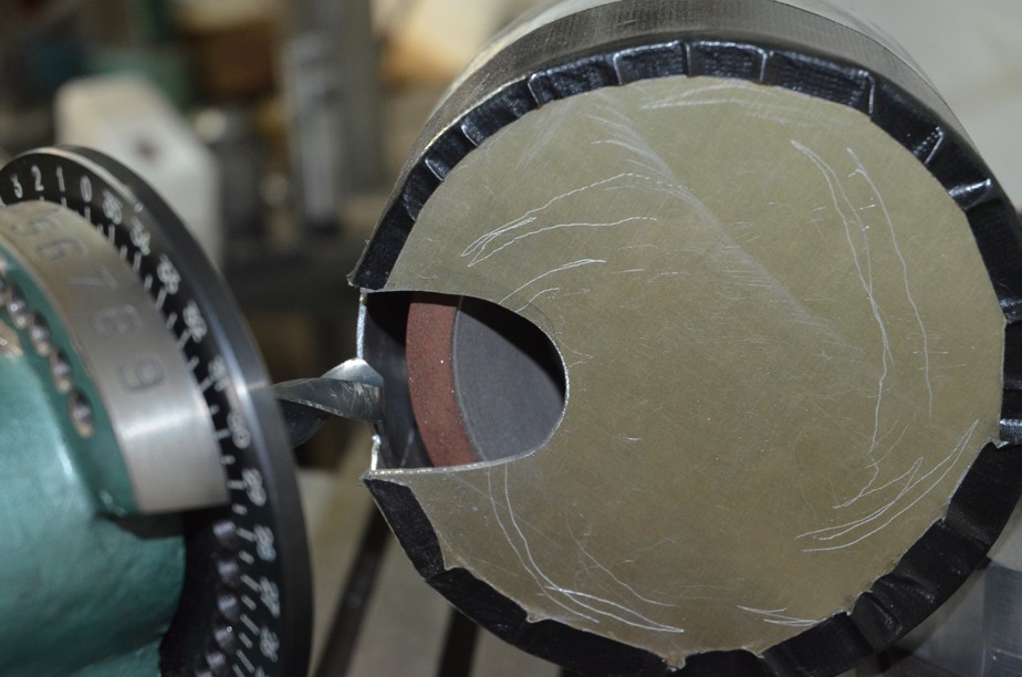
Once that I had established that the tool was working OK I fashioned up a cover for the wheel from some sheet aluminium off-cuts that I had left from making some motorcycle fuel tanks. Not visible in these photos is a tube welded to the rear of the cover for connection to a shop-vac. That catches ALL the grinding dust and the rest of the machine requires no additional protective covering. The Gorilla tape fixing of the outer cover was just a temporary measure while I experimented with the size of the opening. I wanted to keep it as small as possible to keep the entrance air velocity high to carry all dust in, but I needed it large enough not to hinder access for the tool nor hinder vision.
***** I couldn't get any more photos to load. Maybe I exceeded a limit, so I'll try and continue in a following post.*******


 Reply With Quote

Bookmarks