
 LinkBack URL
 About LinkBacks


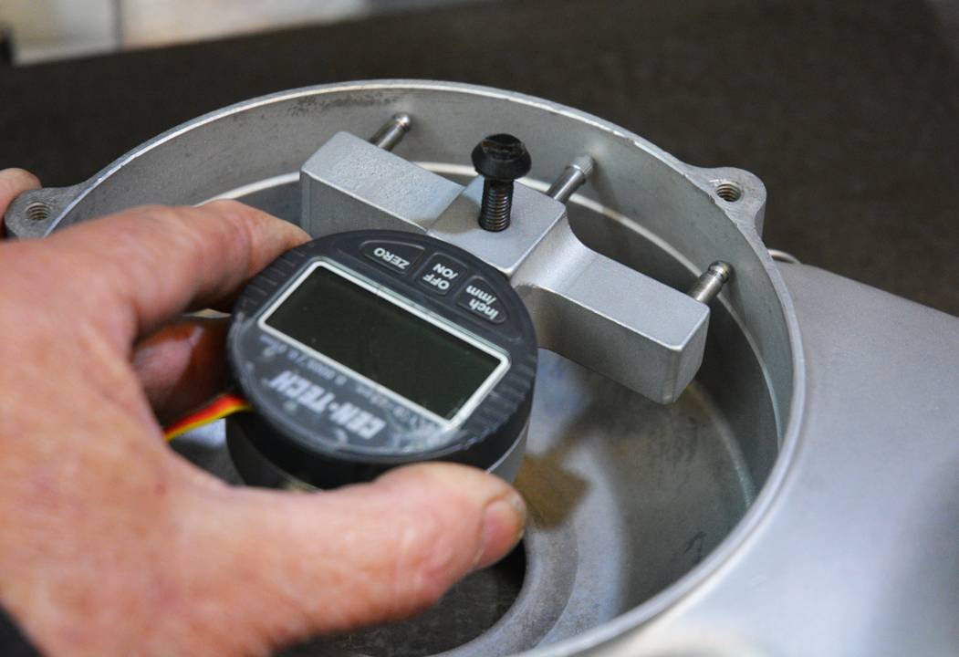
I recently posted about some reverse engineering that I needed to do to replicate some classic motorcycle crankcases at
http://www.homemadetools.net/forum/h...029#post120271
Continuing on from that I needed to measure some corner and other radii, there are many possibilities for such tasks, for example MichaelMoore recently posted his templates at
http://www.homemadetools.net/forum/r...348#post122031
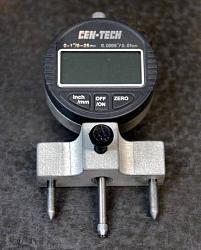
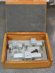
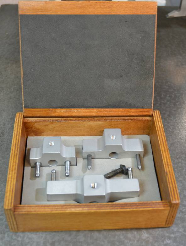
This current post is about a set of radius gauges that I built using a digital gauge as the measuring element.
I have put the full story in a PDF which can be seen and/or downloaded from:
Tony's radius gauge
I have also written a simple bit of software to perform radius calculations and that is linked in the PDF file. I will also add a video in the next few days.


 Reply With Quote

Bookmarks