Free 186 More Best Homemade Tools eBook:  
Get 2,000+ tool plans, full site access, and more.

User Tag List

Page 1 of 2 1 2 LastLast
Results 1 to 10 of 15

Thread: Lathe Spider Chuck at rear of the lathe spindle

  1. #1
    Supporting Member Paul Jones's Avatar
    Join Date
    May 2014
    Location
    Del Mar, California
    Posts
    1,231
    Thanks
    5,810
    Thanked 1,441 Times in 655 Posts

    Paul Jones's Tools

    Lathe Spider Chuck at rear of the lathe spindle

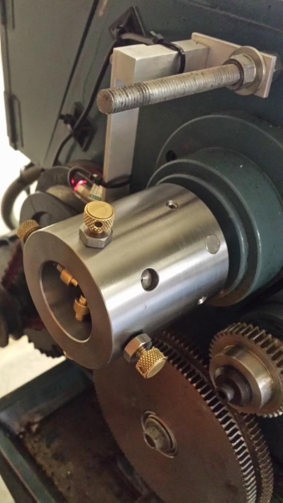
    There are several different meanings to the term “Lathe Spider” published at HomemadeTools.net. The one I built is installed at the rear of the lathe spindle for a 12” swing X 37” gear head lathe and used to support longer rods held in the lathe chuck. The through hole in the spindle is 40 mm (1.575”).

    I have been machining the handles for various “kitchen” tools from small diameter 303 stainless steel rods and using the chuck spider at the rear of the metal lathe spindle helps to keep the small diameter rod from whipping-around (e.g., http://www.homemadetools.net/forum/k...ry-forks-66026 and http://www.homemadetools.net/forum/s...3072#post77395 ). This type of lathe spider chuck is also used in gunsmithing operations for rifle barrels.

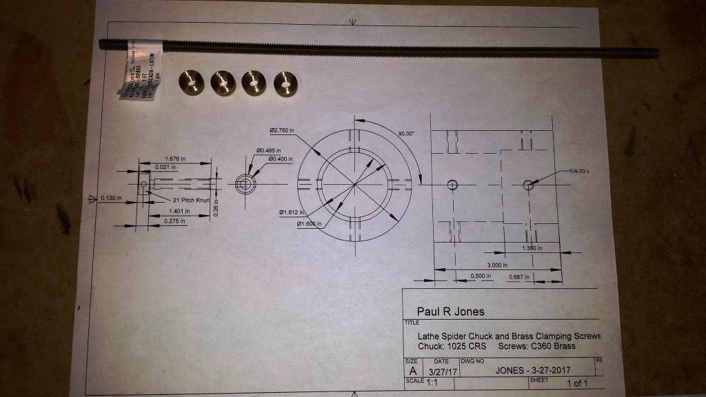
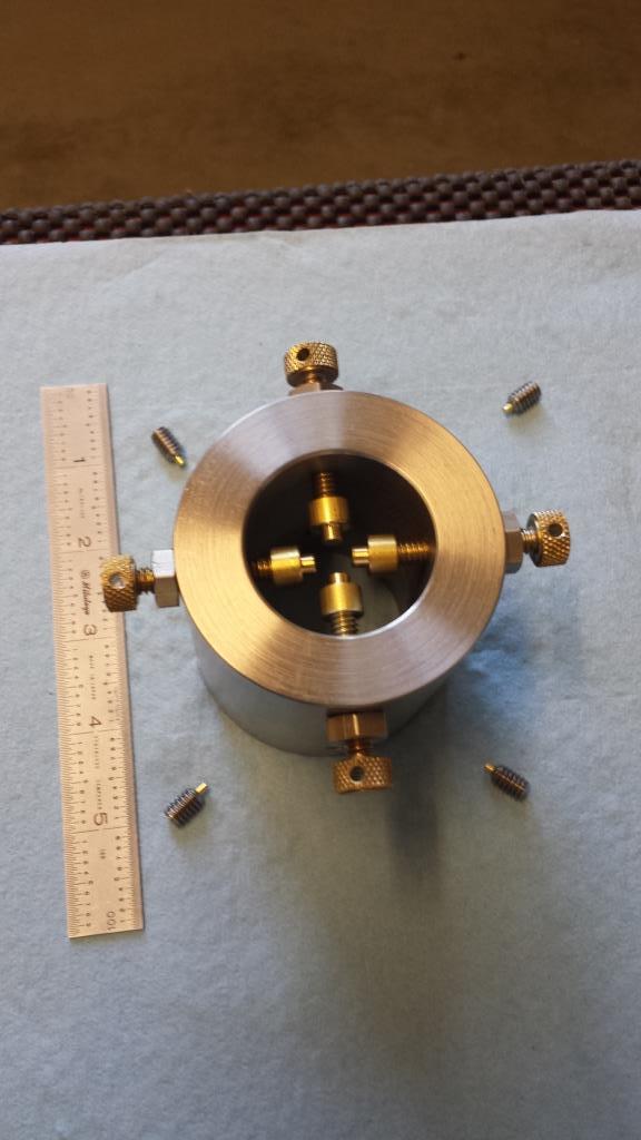
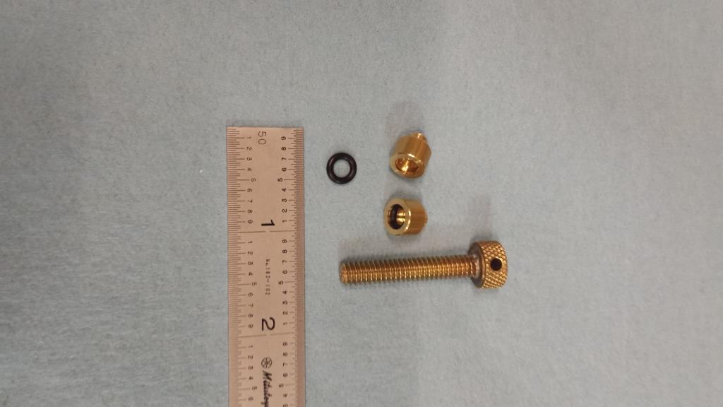
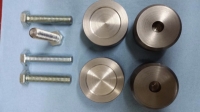
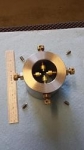
    This lathe spider was machined from 3” dia. 1025 CRS using a left-over steel drop, a 0.5” dia. C360 free machining brass rod, and 0.5” hexagonal free machining 303 stainless steel, and using a section ¼-20 all-thread brass rod. Below are photos of my plans with the four spider knurled adjustment screw caps and ¼-20 all-thread brass rod used as "paperweights" , and the finished chuck spider, and followed by all the machining operations.

    Lathe Spider Chuck at rear of the lathe spindle-lathe-spider-chuck-plans.jpg

    Lathe Spider Chuck at rear of the lathe spindle-lathe-spider-chuck-parts.jpg

    Lathe Spider Chuck at rear of the lathe spindle-lathe-spider-chuck-installed-without-change-gear-cover.jpg

    Lathe Spider Chuck at rear of the lathe spindle-lathe-spider-chuck-installed-large-diameter-rods.jpg

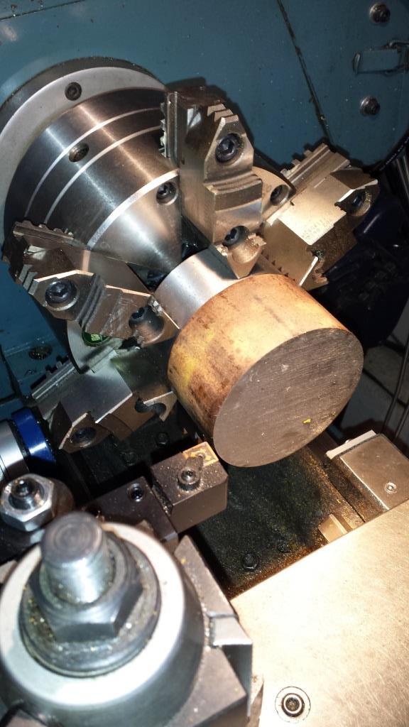
    The first step was to machine the 3” dia. 1025 CRS drop to fit into the end of the lathe spindle and clear the 2.9” diameter opening in the lathe’s back cover for the change gears.

    Lathe Spider Chuck at rear of the lathe spindle-machining-chuck-spider-body-1025-crs.jpg

    Lathe Spider Chuck at rear of the lathe spindle-drilling-out-chuck-spindle-id-before-boring.jpg

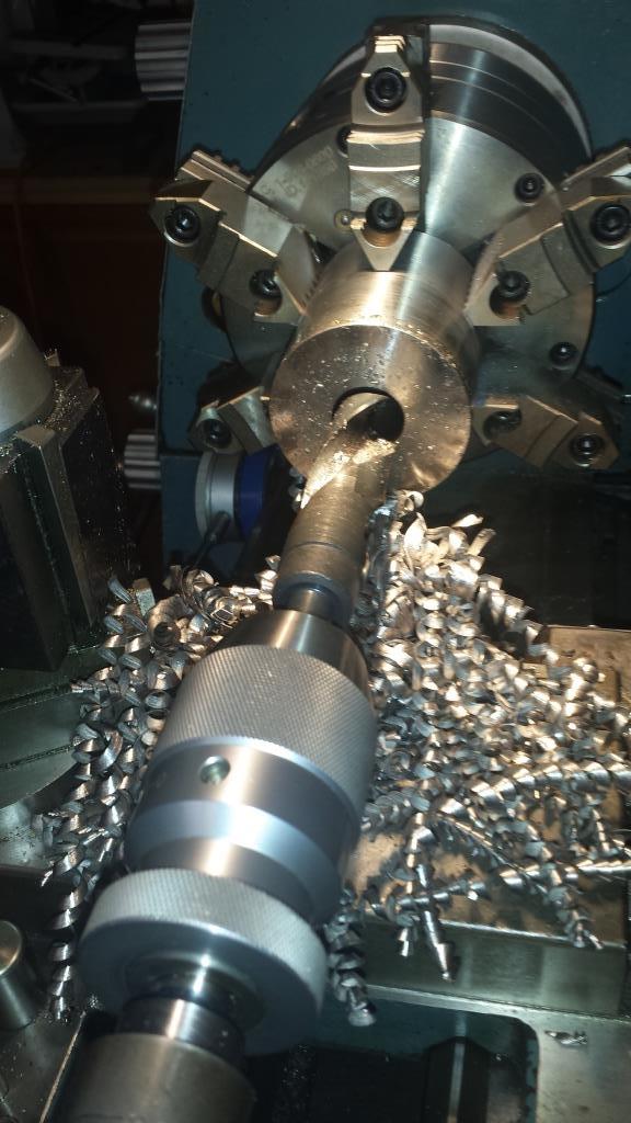
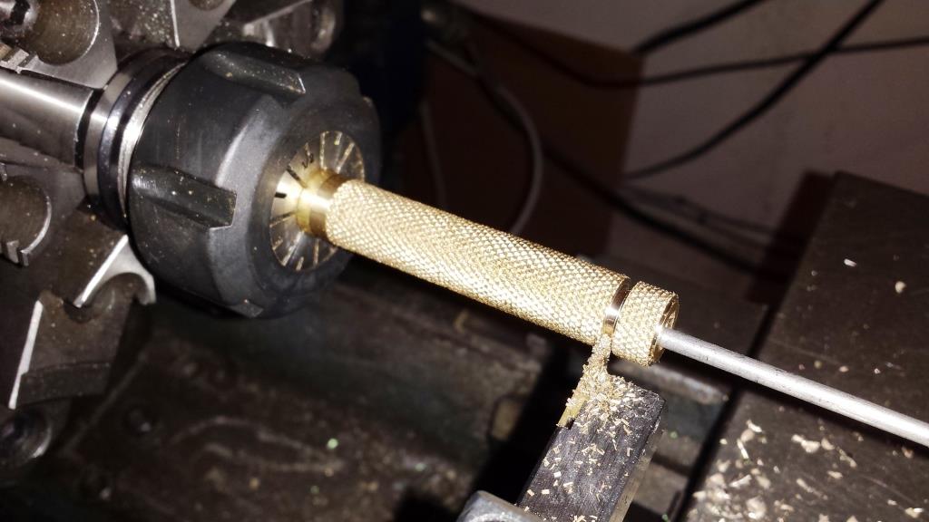
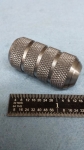
    After test fitting the chuck spider for a less than 0.001” perfect sliding fit to the lathe spindle the next step was to make the brass adjustable holding screws and locking nuts. Rather than machining the adjustable holding screws from a solid C360 brass rod, I made the parts using ¼-20 all-thread brass rod and using a solid C360 brass rod made the knurled the 0.5” diameter adjustment heads with 0.125” cross-holes for doing adjusting.

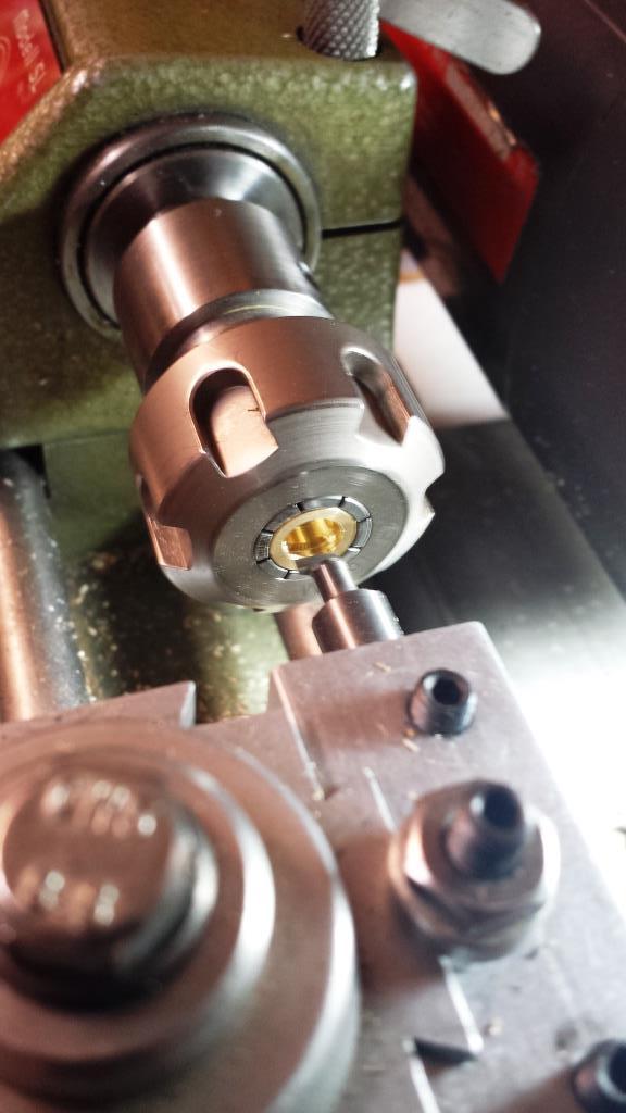
    I also created special brass-ended caps with interior O-rings for the adjustment screws to support small (0.125”) diameter rods. This is the same technique I used for the Starrett V-blocks. (see page 2 to the posting http://www.homemadetools.net/forum/b...blocks-38166-2 ). The brass-ended caps were machined using a modified Unimat SL1000 lathe with a homemade ER16 collet chuck (see for the making of the ER 16 collet chuck http://www.homemadetools.net/forum/e...0273#post57039 ).

    Lathe Spider Chuck at rear of the lathe spindle-using-unimat-sl-1000-machine-o-ring-grove-end-caps.jpg

    Lathe Spider Chuck at rear of the lathe spindle-spider-chuck-adjustment-screws-end-caps.jpg

    The knurled adjustment heads and all thread rods were joined with soft solder. The top of the knurled cap and side indent-details were machined to final dimensions after completing the soldering. This operation was actually much faster than totally machining from a C360 solid brass rod, wasting material, and single point threading the 1/4-20 adjustment screws. This saved a lot of the expensive C360 brass stock where super precision was not necessary.

    Lathe Spider Chuck at rear of the lathe spindle-soldering-knurled-ring-all-thread-before-machining-top-flat.jpg

    Lathe Spider Chuck at rear of the lathe spindle-cutting-off-spider-adjustment-screw-caps.jpg

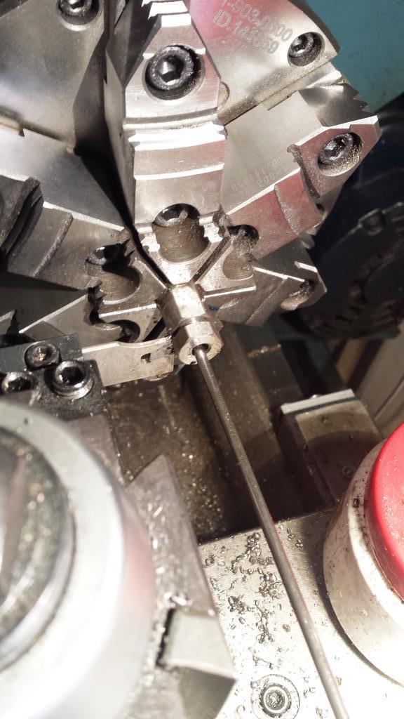
    The locking nuts were machined from 0.5” hexagonal 303 stainless steel rod and machined a 0.20” in width with internal ¼-20 threads (using a 1/4-20 tap while the part was still in the lathe chuck).

    Lathe Spider Chuck at rear of the lathe spindle-cutting-off-lock-nuts-chuck-spider.jpg

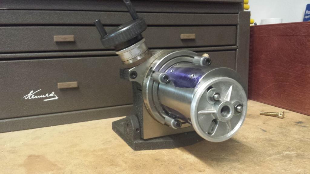
    Next the layout and taping of the ¼-20 threads requiring precise locations were completed using a rotatory table indexed to one degree. The initial layout was completed on a granite plate and height gage. The layout provided guidance on where the holes should be in case I was off by one or two degrees but I relied on the rotatory table for the exact hole locations. The support of the spider chuck required creating special threaded rods and four short hollow rods for side support. Many times these types operations require making special tooling to make the tools and the special tooling can be used for other future work products. I used the Cogsdill Burraway 3/16 diameter tool to debur the outer edge and inner edge of the threaded holes after completing the threading.

    Lathe Spider Chuck at rear of the lathe spindle-rotary-table-setup-chuck-spider.jpg

    Lathe Spider Chuck at rear of the lathe spindle-rotary-table-setup-parts-chuck-spider.jpg

    Lathe Spider Chuck at rear of the lathe spindle-drilling-no.-7-holes-threading-locking-adjustment-screws.jpg

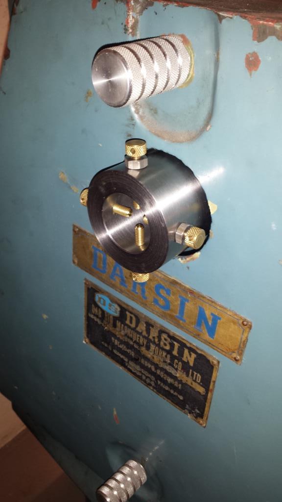
    Finally, the chuck spider must be attached to the lathe spindle using brass tipped set screws to prevent any damage to the lathe spindle. In addition I have Hall Effect Tachometer that uses a small magnet attached to the lathe spindle (see http://www.homemadetools.net/forum/1...6430#post22140 for how this works). This magnet is embedded in the chuck spider and held with Loctite 620.

    Lathe Spider Chuck at rear of the lathe spindle-drilling-hole-magnet-hall-effect-tachometer.jpg

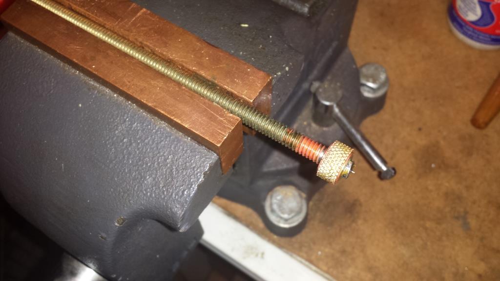
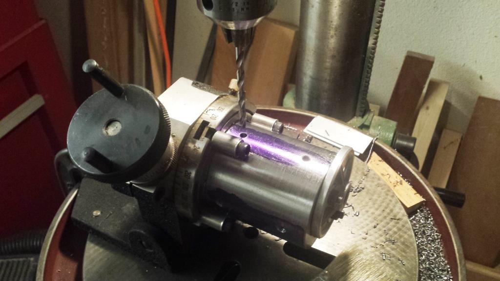
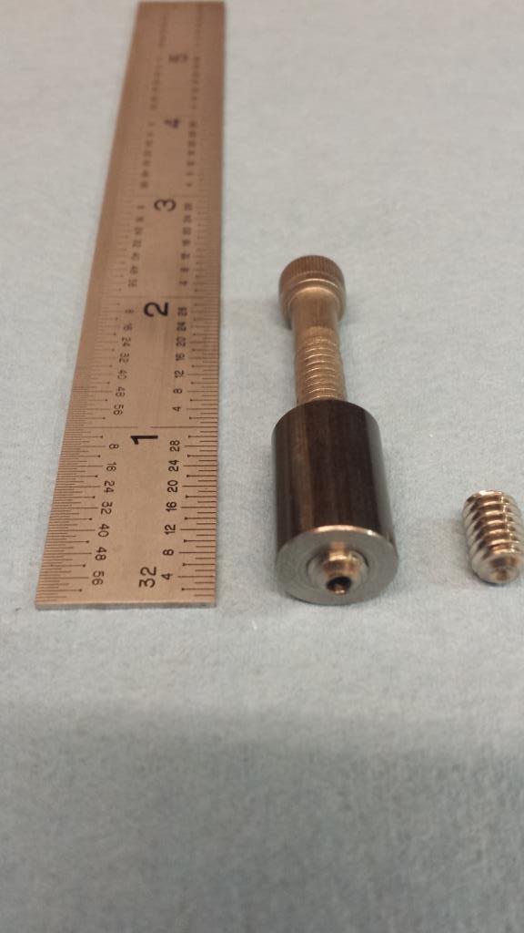
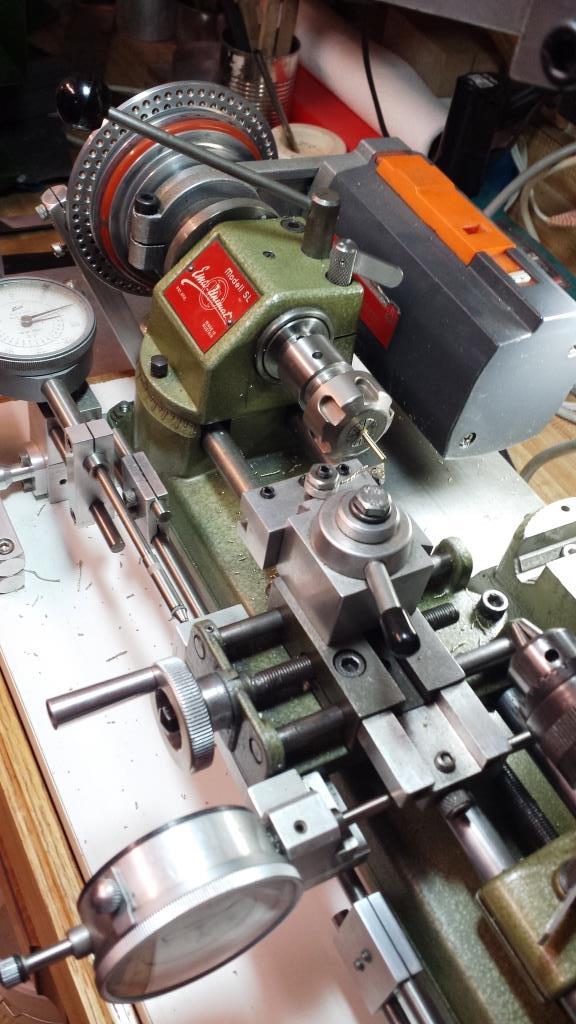
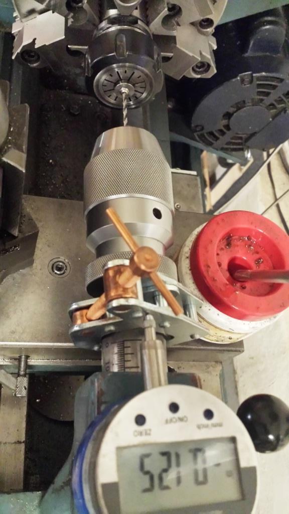
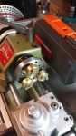
    The picture below shows a simple fixture for holding stainless steel set screws for drilling end holes and was created from 1144 x 0.5” steel rod. The stainless steel set screws are not hardened and easier to drill. The cylinder is internally threaded with a ¼-20 thread and uses a ¼-20 cap screw from the opposite end to lock in the short stainless steel set screw for holding and drilling a 0.094” diameter hole. The hole is 0.125" deep and supports a 3/32" dia. x 0.250 long brass rod (shown below being machined in a highly modified Unimat SL1000 (see http://www.homemadetools.net/forum/m...00-lathe-10111). The Unimat ER16 collet is homemade and one of my best made accessories for this 3" swing small lathe ( http://www.homemadetools.net/forum/e...0273#post57039). The brass rod tips ensure a soft tip for holding the spider chuck onto the lathe spindle without any damage.

    Lathe Spider Chuck at rear of the lathe spindle-fixture-drilling-brass-inset-hole-set-screw.jpg

    Lathe Spider Chuck at rear of the lathe spindle-using-unimat-sl-1000-create-set-screw-brass-inserts.jpg

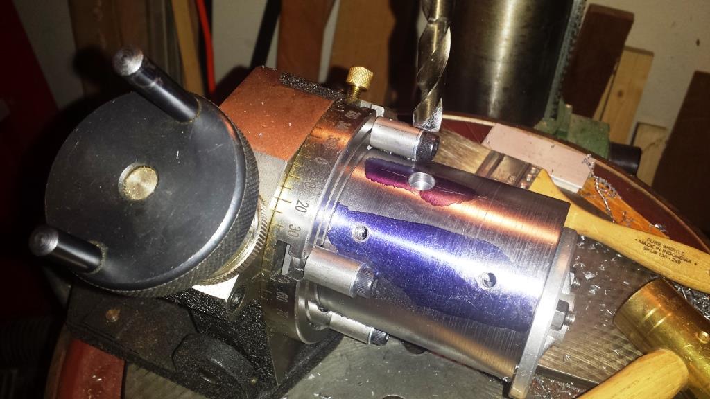
    The photo below shows drilling ends of the stainless screws and the temporary setup for using a 1" depth mag-based digital dial indicator and a small Kant Twist clamp as a back-stop to measure the exact 0.125" depth of drilling.

    Lathe Spider Chuck at rear of the lathe spindle-drilling-set-screw-brass-insert.jpg

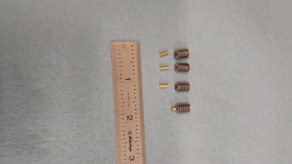
    Below are the assembly of the brass tipped stainless steel set screws.

    Lathe Spider Chuck at rear of the lathe spindle-modified-set-screws-brass-inserts.jpg

    This was a fun project with lots of special parts.
    Thank you for looking,
    Paul

    186 More Best Homemade Tools eBook
    Last edited by Paul Jones; Mar 31, 2018 at 07:21 AM. Reason: completed raw materials list

  2. The Following 14 Users Say Thank You to Paul Jones For This Useful Post:

    aphilipmarcou (Jan 24, 2018), big o (Feb 17, 2018), Doc (Oct 9, 2021), Home-PC (Sep 1, 2022), jjr2001 (Jan 22, 2018), Jon (Jan 22, 2018), LMMasterMariner (Jan 22, 2018), NortonDommi (Jan 23, 2018), olderdan (Jan 23, 2018), PJs (Jan 23, 2018), rossbotics (Jan 22, 2018), Seedtick (Jan 22, 2018), thehomeengineer (Jan 22, 2018), Toolmaker51 (Jan 22, 2018)

  3. #2
    Supporting Member Toolmaker51's Avatar
    Join Date
    Feb 2016
    Location
    Midwest USA
    Posts
    5,331
    Thanks
    7,042
    Thanked 2,981 Times in 1,893 Posts

    Toolmaker51's Tools
    Lathes benefit from a few particular tools not supplied by manufacturers. Spiders, stops and centerline gauge for tool height are my top 3.
    Spiders are overlooked projects; until they are needed. Guide bushings aren't universal being rather one-size affairs. Scrambling for a fix, not remedy just stop-gap is no solution. Smaller lathes = smaller chuck jaws; less clamping surface allows little diameters to whip.
    Many find a removable stop, fitted inside spindle another must-have. Usually flat ended, a conical bore picks up rod ends and support all but springiest materials.
    There are many tool height references on HMT, enter "tool height gauge" if you dare!

    2000 Tool Plans
    Sincerely,
    Toolmaker51
    ...we'll learn more by wandering than searching...

  4. The Following 5 Users Say Thank You to Toolmaker51 For This Useful Post:

    Home-PC (Sep 1, 2022), jjr2001 (Jan 22, 2018), NortonDommi (Jan 23, 2018), Paul Jones (Jan 22, 2018), PJs (Jan 23, 2018)

  5. #3
    Supporting Member jjr2001's Avatar
    Join Date
    Jun 2016
    Posts
    915
    Thanks
    1,182
    Thanked 2,045 Times in 553 Posts

    jjr2001's Tools
    Nice Spyder Paul, I like the tool you made to retain the brass screws while drilling the end. I can see variations that could be used to cutoff to a specific length, Point the end of the screw and "dog point" the screw. Your method of drilling the end and using a pin makes a nice dog point with replaceable tip.

    Cheers, JR

  6. The Following 2 Users Say Thank You to jjr2001 For This Useful Post:

    Paul Jones (Jan 22, 2018), PJs (Jan 23, 2018)

  7. #4
    Supporting Member rossbotics's Avatar
    Join Date
    Dec 2013
    Location
    Florida
    Posts
    730
    Thanks
    1,019
    Thanked 1,647 Times in 402 Posts

    rossbotics's Tools
    Hi Paul
    Good work buddy, nicely presented, great details and beautiful work as usual,

    Thanks for sharing
    Comments are always welcome
    Doug

    Subscribe to my you tube channel

    https://www.youtube.com/channel/UCDD..._as=subscriber


    Tool Plans for Sale by rossbotics


  8. The Following 2 Users Say Thank You to rossbotics For This Useful Post:

    Paul Jones (Jan 23, 2018), PJs (Jan 23, 2018)

  9. #5
    Supporting Member Paul Jones's Avatar
    Join Date
    May 2014
    Location
    Del Mar, California
    Posts
    1,231
    Thanks
    5,810
    Thanked 1,441 Times in 655 Posts

    Paul Jones's Tools
    Doug,
    Thank you for the compliments. I enjoy seeing all your fantastic tool projects as well.

    I have been using the lathe spider chuck lately for machining 3/8" diameter 303 stainless steel knurled handles for a series of "kitchen" tools that include cake testers, cheese spreading knives, drink stirrers, pickle forks, demitasse spoons, and pastry forks for my wife and friends. I will publish the photos in an another series. I am now beginning work on a long reach fish venting tool with similar handles and protective stainless steel tube cover. These aren't the typical HMT tools but all fun projects to work on and much appreciated by all.

    Regards,
    Paul
    Last edited by Paul Jones; Jan 23, 2018 at 01:45 PM.

  10. #6
    Supporting Member Paul Jones's Avatar
    Join Date
    May 2014
    Location
    Del Mar, California
    Posts
    1,231
    Thanks
    5,810
    Thanked 1,441 Times in 655 Posts

    Paul Jones's Tools
    JR,

    Thank you for the compliments. Creating a "dog" point would work well. I have used a similar drilling techniques for adding brass tips to threaded steel locking screws for some of my 6" and 12" swing lathes cross slides and compound slides (see http://www.homemadetools.net/forum/l...screws-30133-2 ). It works well, does not "mushroom" at the brass tip and protects the cast iron and steel sliding surfaces from scoring or dimples.

    Regards,
    Paul

  11. The Following User Says Thank You to Paul Jones For This Useful Post:

    jjr2001 (Jan 23, 2018)

  12. #7

    Join Date
    Sep 2016
    Posts
    7
    Thanks
    0
    Thanked 11 Times in 7 Posts

    Topos's Tools
    Thank you for the superlative presentation.
    Compliments on your enviable machining skills.
    Learned some new tricks from your set up.
    Best!

  13. The Following User Says Thank You to Topos For This Useful Post:

    Paul Jones (Jan 23, 2018)

  14. #8
    PJs
    PJs is offline
    Supporting Member PJs's Avatar
    Join Date
    Sep 2014
    Location
    Northern CA
    Posts
    1,841
    Thanks
    8,337
    Thanked 1,118 Times in 718 Posts

    PJs's Tools
    As always an Exemplary build and write up Paul! Such detail with the O-rings in the caps!! Excellent & simple fixture from the 1144, and your soft tip dog points are beautiful! Thanks for sharing another precision, well thought out and beautifully executed project!

  15. The Following User Says Thank You to PJs For This Useful Post:

    Paul Jones (Jan 23, 2018)

  16. #9
    Supporting Member Paul Jones's Avatar
    Join Date
    May 2014
    Location
    Del Mar, California
    Posts
    1,231
    Thanks
    5,810
    Thanked 1,441 Times in 655 Posts

    Paul Jones's Tools
    Thank you PJs and I wish you and your family a happy New Year.

    I have missed your wonderful comments and explanations to our discussion threads. Nice to see you back in the discussions.

    Regards,
    Paul

  17. The Following User Says Thank You to Paul Jones For This Useful Post:

    PJs (Jan 23, 2018)

  18. #10
    Content Editor
    Supporting Member
    DIYer's Avatar
    Join Date
    Aug 2013
    Posts
    3,056
    Thanks
    772
    Thanked 1,852 Times in 1,653 Posts


    Thanks Paul Jones! We've added your Lathe Spider to our Workholding category,
    as well as to your builder page: Paul Jones's Homemade Tools. Your receipt:


  19. The Following 2 Users Say Thank You to DIYer For This Useful Post:

    Home-PC (Sep 1, 2022), Paul Jones (Jan 25, 2018)

Thread Information

Users Browsing this Thread

There are currently 1 users browsing this thread. (0 members and 1 guests)

Tags for this Thread

Bookmarks

Posting Permissions

  • You may not post new threads
  • You may not post replies
  • You may not post attachments
  • You may not edit your posts
  •