 LinkBack URL
 About LinkBacks
Nice work.


I did warn you: Here's loads of pictures taken while making a new fuel distributor block. It's little smaller than the first one I made and routes the hoses from petcock to carb nice and neatly, it also levels the fuel on both sides of the tank so one carb doesn't run dry when the fuel level gets low.
The block is drilled through left to right 5.5mm and has barbs machined on the end to take the 8mm hose going to the carbs. Two 6mm brass barbs are pressed in place on the front which take the hoses from the petcock via a couple of inline filters.
asterix (Dec 22, 2022)
Heres the process used making the air filters. I took sizes of the first filter I made and replicated them to the second. This time I took lots of pictures to outline the steps in making them. I cut a 15mm slice off the 101.6mm lump of ally and turned down one end to 97.4mm, then cut a piece of 1.7mm sheet to around 111-mm in diameter, stuck them together and bashed the overhang until there wasnt one. I have to use my left hand now, as the right elbow complains. Sound easy, but its not, out of every 10 strikes, I think I miss about nine.
Once formed, I mounted it in the four jaw, and turned the overhang down to 3mm, then smoothed out all the scratches and what not with sand paper, finishing off with the random orbital sander with 240 grit.
Next, I mounted the 15mm slab in the three jaw using the turned down area and drilled through with a 25mm bit, machined the outer diameter to 101.4mm, machined out the centre leaving a 2mm wide lip on the periphery, 3mm deep, then bored out the 25mm centre hole to 57.3mm to fit the 57.4 mm carb bell mouth. .10 mm proved a little tight, .07 would have been better I think.
I flipped the slab over and mounted it in the four jaw, then spent a couple of hours trying to centre the damn thing, then turned down the inner mounting ring so its 8mm wide and the flat body of the filter 2mm thick. Final step, turn down the inner mounting ring so its 9.8mm deep.
The cutting tool was then centred., spot on, and used to scribe a line across the back of the centre mounting ring. After removing from the chuck I found the centre point using a calliper, centre popped it, mounted it on the mill and drilled the centre pops with a 4mm bit, then mounted it on the pedestal drill, centred the holes and tapped the 4mm holes with a 5mm x .8 tap. The plate was then turned on its side, and drilled and tapped in the centre of the centre ring at 90degrees to the other two holes on the face.
The piece was mounted in the three jaw again and using 240 grit any cutting ridges were smoothed over, then both plates were polished.
The knurled securing nuts were turned up from a piece of 20mm stock, tapped 5mm and then knurled using the scissor knurler. These were mostly done by eye, so wont be absolutely identical. Youd need a calliper to pick up the difference though, so good are my four eyes.
The carb body was mounted in the three jaw and a file used to remove the ridge at the beginning of the bell mouth. The face of the bell mouth was pretty rough, so I took the time to smooth that with some emery. The turned piece was located over the bell mouth, the assembly was then stuck in the vice and pressed into place.
The lead into the bell mouth is flat, so not a perfect shape for induction. You can recess the filter lower on the bell mouth, creating a bit of a lip on the outer periphery of the bell mouth to improve induction, but realistically the improvement in induction wouldnt be worth the time.
Both filters fit well and the hoses from the fuel distributor block lead over the filters nice and neatly. Happy with the outcome, except the inner knurled nuts are a little difficult to get to, probably due more to the fact my fingers are fused, but I can turn them with a little bit of messing around, better still, use the wife, her fingers arent fused. Ive yet to get some perforated sheet metal to replace the stainless crap I used to keep the foam in place.
asterix (Dec 26, 2022), Jon (Dec 26, 2022), nova_robotics (Dec 26, 2022), sossol (Dec 26, 2022)
Slaved away today - making a clutch slave cylinder. I made it so it sits in the left cover, protruding through the clutch screw actuatorr hole. I managed to get the tolerances better than the caliper tolerances: The bore is dead on 25mm, the piston dead on 24.97, a really nice fit.
I couldn't find any seals similar to the caliper seals, but found a hydraulic pressure seal and dust seal, but I have to find a 25 mm internal circlip before cutting the circlip groove. I also,have to drill a couple of holes in the collar to suit the holes in the side cover, then bore out the hole in the cover to 30mm and drill out the M5 securing threads. Once done two M5 Allen's will bolt through the outside of the cover, holding the slave cylinder in place.
I did make one mistake, got carried away on the lathe and cut the collar down to 18mm, that only leaves a 6 mm threaded hole in the collar of the slave cylinder. Hopefully this may work as the screws are really on locating pegs.
Before modifying the side cover I'll order a hydraulic hose. Not sure what size master cylinder to get, but I'll try the slave out on the 17mm braker master cylinder first, that should give a clue, unless of course, someone here knows what size master to go with the 25mm slave for a nice light clutch pull: Fused fingers so grip isn't the best.
I'm hoping to find a pair of matching radial clutch/brake master cylinders.
I have seen matched pairs of clutch/brake master cylinders advertised on Aliexpress if you do not mind getting stuff from there.
I think that you will need to get the smallest master cylinder piston that you can find. 25 mm slave is not very large so you need a small master to get a light feel, but if you go too light then you will not have enough movement to free the clutch. Fortunately, swapping those horrible Yamaha scroll release mechanisms for hydraulics means that you have much less lost motion, and so it becomes easier to combine a light feel with sufficient movement.
To put some numbers to it. 12 mm is a common master cyl. size. That is near 1/2 of your slave so the force and distance ratios will be near 4. The release force will be 4 times that on the master piston. I do not know if 10 mm masters are available but that would increase the ratios to 6.25. Of course the hand lever ratio will reduce the hand force further.
I once sleeved a master cylinder to get a smaller piston, I found seals from a GoKart brake.
asterix (Jan 17, 2023)
Nothing against Chinese here, they make some exceptional stuff, my stator and rotor are made in China. Most of the stuff you buy in your local, thinking its locally made, is made in China, it just has the locals sticker on it. People are so easilly fooled, very difficult to avoid Chinese made.
But, I may not get to use the slave. After looking around for master cylinders, I couldn't find matching clutch/brake masters of the size I'll need (12/17mm), so it'll be either non matching masters, or, an easy pull for the stock cable

I use Chinese stators in my bikes, at one tenth the cost of 'factory' Honda, and a three times that for 'factory' BMW, it's a no brainer, and just like the factory stators full vacuum impregnation with good epoxy to stop magnetically induced 'fretting' rubbing through the insulation is worthwhile, still looking for a pump to do that.Originally Posted by th62

I agree about chinese stuff, it is almost impossible not to buy it. My comment was not against their stuff but just an acknowledgement that some people are not happy buying from Aliexpress.
For Xmas I was given a chinese tilting table and a chinese rotary table. The tilting table was crap, over 1 mm out of level over the length of the table and there was considerable rock when it was put on a surface plate. The base and top had mismatched radii and most surfaces looked like they had been "machined" on a linisher not a grinder nor mill. The castings were very good though and after machining the whole thing I have a nice table. On the other hand the rotab came with a calibration certificate which I confirmed and was machined to a high standard and had no need of improvement. It is hard to tell in advance what the quality will be on any particular item.
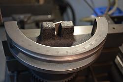
Click image for full size.
Showing the extent of the radii mismatch on the tilting table.
About the master cylinders. It is not difficult to sleeve them down, just a question of finding suitable seals in the diameter required. If you sleeve then it is beneficial to use a ball hone as the final finishing on the bore. Around 2009 I was gainfully employed (an unusual occurrence, because I have mainly been self employed) and I designed an unusual braking system which required custom cylinders. I had these on test for many days with thousands of applications per day. Tests were done with different bore finishes, those that had been done with a ball hone were always better.
Last edited by tonyfoale; Jan 18, 2023 at 07:59 AM.
asterix (Jan 18, 2023)
The problem with boring out masters is getting the right piston and seals to fit the cylinder design. Not all master have the holes in the same position. So, finding a piston to suit with the right number of seals and seals set in the right place isn't as easy as it would seem, Unfortunately, there is no índustry standard with regards to design and placement, each manufacturer following their own design. It's fine if you have acces to dozens of cylinders and pistons. Unfortunately I don't have that access, so have to 'wing'it!
Last edited by th62; Jan 18, 2023 at 02:29 PM.
Now the bike is almost finished, just needs the seat covered and tyres, so I put on my glasses and cast a critical eye over it. Story of my life never, ever happy, and what do you know, I found a few things Im not happy with, so, I can start making parts for it again, whoo hoo!. First up was a new spin on filter/cooler. The current one totally underwhelms me: hoses look untidy, the spin on filter mount looks too blocky, so, that went in the bin. One of the screws holding the mount to the engine bracket was a bit hard to get at, so, the right engine mount went in the bin. The cooler bracket is just plain terrible, didnt like the mounting method nor the look of it, plus the rubbers I felt were too small, so that also went in the bin, along with the left engine mount.
So, back to work: first up was a new spin on filter mount, I put a little shape into this one: rounded the edges, turned a cone on top and pressed the inlet spigot into the side of the mount, so the outlet hose from the front of right engine cover is only around 4long and attaches to the inlet spigot of the spin on mount on the side, just in front of the engine mount. Much more neaterer!
Next came some new engine brackets. The spin on mount is still mounted in the same manner, just set further back, so, the engine bracket protrudes further back, almost touching the engine case. This allows the rear allen head that was hiding behind the down tube to be moved further back, so now it is to thebrearnof the downtube and thus easy to get at.
Next came the cooler mount, the original I made was a piece of 3mm ally, bent at a right angle and bolted to the front of the engine brackets via four allen heads. Didnt like that, so I extended a goose neck on the front of the engine brackets out about 30mm and drilled and tapped holes in top for mounting the cooler bracket.
The cooler bracket, is now just a flat section of 3mm ally, with larger holes drilled to take bigger, thicker gromets and is secured to the top of the engine mount goose neck protrusions via four stainless button heads. To mount the cooler to the bracket I spun up four threaded T nuts that are inserted into the gromets from underneath and the four long bolts secure the cooler to the top of the bracket. The T nuts prevent the gromets from being squished too much.
Now I just have the one long hose over the engine bracket connecting the cooler outlet spigot to the right engine cover. A hose connects the spin on mount spigot on top to the inlet on the cooler. Ill retain the black rubber hoses as I dont like the look of braided hose: to silvery and hard to keep clean down there with all the road debris and the black hose is a little less intrusive.
greenie (Mar 2, 2023), nova_robotics (Mar 2, 2023), tonyfoale (Mar 24, 2023)
There are currently 1 users browsing this thread. (0 members and 1 guests)
 Posting Permissions


 Reply With Quote

Bookmarks