Free 186 More Best Homemade Tools eBook:  
Get 2,000+ tool plans, full site access, and more.

User Tag List

Page 27 of 32 FirstFirst ... 3 4 5 6 7 8 9 10 11 12 13 14 15 16 17 18 19 20 21 22 23 24 25 26 27 28 29 30 31 32 LastLast
Results 261 to 270 of 314

Thread: 1974 XS/TX650 rebuild

  1. #261
    Supporting Member tonyfoale's Avatar
    Join Date
    Nov 2016
    Location
    Spain
    Posts
    1,566
    Thanks
    690
    Thanked 2,648 Times in 709 Posts

    tonyfoale's Tools
    I agree about chinese stuff, it is almost impossible not to buy it. My comment was not against their stuff but just an acknowledgement that some people are not happy buying from Aliexpress.

    For Xmas I was given a chinese tilting table and a chinese rotary table. The tilting table was crap, over 1 mm out of level over the length of the table and there was considerable rock when it was put on a surface plate. The base and top had mismatched radii and most surfaces looked like they had been "machined" on a linisher not a grinder nor mill. The castings were very good though and after machining the whole thing I have a nice table. On the other hand the rotab came with a calibration certificate which I confirmed and was machined to a high standard and had no need of improvement. It is hard to tell in advance what the quality will be on any particular item.
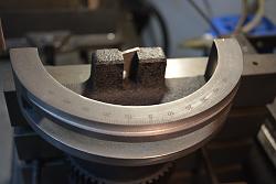
    1974 XS/TX650 rebuild-dsc_4803.jpg 1974 XS/TX650 rebuild-dsc_4813.jpg Click image for full size.
    Showing the extent of the radii mismatch on the tilting table.

    About the master cylinders. It is not difficult to sleeve them down, just a question of finding suitable seals in the diameter required. If you sleeve then it is beneficial to use a ball hone as the final finishing on the bore. Around 2009 I was gainfully employed (an unusual occurrence, because I have mainly been self employed) and I designed an unusual braking system which required custom cylinders. I had these on test for many days with thousands of applications per day. Tests were done with different bore finishes, those that had been done with a ball hone were always better.

    186 More Best Homemade Tools eBook

  2. The Following User Says Thank You to tonyfoale For This Useful Post:

    asterix (Jan 18, 2023)

  3. #262
    Supporting Member th62's Avatar
    Join Date
    Oct 2015
    Posts
    270
    Thanks
    0
    Thanked 503 Times in 168 Posts

    th62's Tools
    The problem with boring out masters is getting the right piston and seals to fit the cylinder design. Not all master have the holes in the same position. So, finding a piston to suit with the right number of seals and seals set in the right place isn't as easy as it would seem, Unfortunately, there is no índustry standard with regards to design and placement, each manufacturer following their own design. It's fine if you have acces to dozens of cylinders and pistons. Unfortunately I don't have that access, so have to 'wing'it!

    2000 Tool Plans
    Last edited by th62; Jan 18, 2023 at 02:29 PM.

  4. #263
    Supporting Member th62's Avatar
    Join Date
    Oct 2015
    Posts
    270
    Thanks
    0
    Thanked 503 Times in 168 Posts

    th62's Tools
    Now the bike is almost finished, just needs the seat covered and tyres, so I put on my glasses and cast a critical eye over it. Story of my life – never, ever happy, and what do you know, I found a few things I’m not happy with, so, I can start making parts for it again, whoo hoo!. First up was a new spin on filter/cooler. The current one totally underwhelms me: hoses look untidy, the spin on filter mount looks too blocky, so, that went in the bin. One of the screws holding the mount to the engine bracket was a bit hard to get at, so, the right engine mount went in the bin. The cooler bracket is just plain terrible, didn’t like the mounting method nor the look of it, plus the rubbers I felt were too small, so that also went in the bin, along with the left engine mount.

    So, back to work: first up was a new spin on filter mount, I put a little shape into this one: rounded the edges, turned a cone on top and pressed the inlet spigot into the side of the mount, so the outlet hose from the front of right engine cover is only around 4’long and attaches to the inlet spigot of the spin on mount on the side, just in front of the engine mount. Much more neaterer!

    Next came some new engine brackets. The spin on mount is still mounted in the same manner, just set further back, so, the engine bracket protrudes further back, almost touching the engine case. This allows the rear allen head that was hiding behind the down tube to be moved further back, so now it is to thebrearnof the downtube and thus easy to get at.

    Next came the cooler mount, the original I made was a piece of 3mm ally, bent at a right angle and bolted to the front of the engine brackets via four allen heads. Didn’t like that, so I extended a goose neck on the front of the engine brackets out about 30mm and drilled and tapped holes in top for mounting the cooler bracket.

    The cooler bracket, is now just a flat section of 3mm ally, with larger holes drilled to take bigger, thicker gromets and is secured to the top of the engine mount goose neck protrusions via four stainless button heads. To mount the cooler to the bracket I spun up four threaded T nuts that are inserted into the gromets from underneath and the four long bolts secure the cooler to the top of the bracket. The T nuts prevent the gromets from being squished too much.

    Now I just have the one long hose over the engine bracket connecting the cooler outlet spigot to the right engine cover. A hose connects the spin on mount spigot on top to the inlet on the cooler. I’ll retain the black rubber hoses as I don’t like the look of braided hose: to silvery and hard to keep clean down there with all the road debris and the black hose is a little less intrusive.
    Attached Thumbnails Attached Thumbnails 1974 XS/TX650 rebuild-win_20230222_16_06_18_pro.jpg   1974 XS/TX650 rebuild-win_20230223_10_55_06_pro.jpg   1974 XS/TX650 rebuild-win_20230223_15_23_06_pro.jpg   1974 XS/TX650 rebuild-win_20230223_15_23_21_pro.jpg   1974 XS/TX650 rebuild-win_20230223_15_23_55_pro.jpg  

    1974 XS/TX650 rebuild-win_20230227_10_23_13_pro.jpg   1974 XS/TX650 rebuild-win_20230227_10_23_54_pro.jpg   1974 XS/TX650 rebuild-win_20230301_11_51_20_pro.jpg   1974 XS/TX650 rebuild-win_20230301_15_24_10_pro.jpg   1974 XS/TX650 rebuild-win_20230223_15_59_35_pro.jpg  

    1974 XS/TX650 rebuild-win_20230301_15_44_32_pro.jpg   1974 XS/TX650 rebuild-win_20230301_15_44_49_pro.jpg   1974 XS/TX650 rebuild-win_20230301_15_56_03_pro.jpg   1974 XS/TX650 rebuild-win_20230301_16_25_13_pro.jpg   1974 XS/TX650 rebuild-win_20230301_16_25_26_pro.jpg  

    1974 XS/TX650 rebuild-win_20230301_17_20_12_pro.jpg  

  5. The Following 3 Users Say Thank You to th62 For This Useful Post:

    greenie (Mar 2, 2023), nova_robotics (Mar 2, 2023), tonyfoale (Mar 24, 2023)

  6. #264
    Supporting Member th62's Avatar
    Join Date
    Oct 2015
    Posts
    270
    Thanks
    0
    Thanked 503 Times in 168 Posts

    th62's Tools
    I managed to drop the seat, so had to strip and straighten it, the calipers crinkled in a couple of spots, must had dropped some brake fluid on them, so I also stripped and repainted them. 2k paint, so I'll wait a couple of weeks before taking it in to get covered.
    Attached Thumbnails Attached Thumbnails 1974 XS/TX650 rebuild-win_20230226_10_35_31_pro.jpg   1974 XS/TX650 rebuild-333209032_170839075691897_9082914204823380744_n-1-.jpg  

  7. #265
    Supporting Member th62's Avatar
    Join Date
    Oct 2015
    Posts
    270
    Thanks
    0
    Thanked 503 Times in 168 Posts

    th62's Tools
    Catch can build.

    I was going to plumb the read valve engine breather into the pancake filters, but didn't like the idea of breathing sump gasses into the inlet, so, I made this catch can.

    Not quite finished yet, I rushed it toward the end to see what it'd look like, happy with the result, So I'll probably build a neater one, with a few changes of course.

    Matches the pancake filters, but almost unnoticeable
    Attached Thumbnails Attached Thumbnails 1974 XS/TX650 rebuild-win_20230311_13_51_21_pro.jpg   1974 XS/TX650 rebuild-win_20230311_14_39_35_pro.jpg   1974 XS/TX650 rebuild-win_20230311_14_40_07_pro.jpg   1974 XS/TX650 rebuild-win_20230311_16_19_54_pro.jpg   1974 XS/TX650 rebuild-win_20230312_15_26_10_pro.jpg  

    1974 XS/TX650 rebuild-win_20230312_15_37_07_pro.jpg   1974 XS/TX650 rebuild-win_20230312_15_38_24_pro.jpg  

  8. #266
    Supporting Member th62's Avatar
    Join Date
    Oct 2015
    Posts
    270
    Thanks
    0
    Thanked 503 Times in 168 Posts

    th62's Tools
    So, I finally settled on a catch can design and built it. The first one was simply too big, creating mounting problems, so that was binned. The final one is made of 42mm tube with four baffles. Instead of welding the baffles inside of the tube, I fixed them together with a 4mm screwed and peened the end so it wouldn’t come apart, the baffle cartridge was then pressed into place resting on top of the intake tube so it won’t float around. The intake tube stretches across the diameter of the 42mm tube and has three exit holes underneath. For the blowby gas to escape it has to exit via the four baffles and finally through some stainless mesh before exiting through the air filter on top, set between the two carb filters.

    I’ve gone with a remote empty point via a tap connected to the catch can by a rubber hose. The filtering medium inside the can is replaceable via the top plate secured on top by four 4mm stainless allens. The can is mounted to an aluminium bracket by two rubber gromets and two threaded T nuts to stop the gromet from being squished too far, then fixed to the right, rear engine bracket.

    Mounting the can proved a little troublesome: behind the motor over top of the swing arm pivot is the only place I could find to mount it. To make it less noticeable I painted it black and welded an outlet on the side so I could mount the final filter between the two carb filters. It is only a small catch can with around 220ml capacity, that’s in total of course, realistically only around 100mm under the baffles. If it proves too small, I can fit a larger container under the swingarm connected to the catch can outlet by a rubber hose.

    It’s very busy in this are area now, two carbs, three filters, catch can, fuel distributor block, making it a little difficult to remove the air filter caps.
    Attached Thumbnails Attached Thumbnails 1974 XS/TX650 rebuild-1.jpg   1974 XS/TX650 rebuild-2.jpg   1974 XS/TX650 rebuild-4.jpg   1974 XS/TX650 rebuild-5.jpg   1974 XS/TX650 rebuild-6.jpg  

    1974 XS/TX650 rebuild-win_20230324_10_06_19_pro.jpg   1974 XS/TX650 rebuild-win_20230324_11_10_04_pro.jpg   1974 XS/TX650 rebuild-win_20230324_11_12_24_pro.jpg   1974 XS/TX650 rebuild-win_20230324_12_04_01_pro.jpg   1974 XS/TX650 rebuild-win_20230324_12_04_31_pro.jpg  

    1974 XS/TX650 rebuild-win_20230324_12_04_51_pro.jpg  

  9. The Following 4 Users Say Thank You to th62 For This Useful Post:

    greenie (Mar 24, 2023), nova_robotics (Mar 24, 2023), Rikk (Mar 24, 2023), tonyfoale (Mar 24, 2023)

  10. #267
    Supporting Member th62's Avatar
    Join Date
    Oct 2015
    Posts
    270
    Thanks
    0
    Thanked 503 Times in 168 Posts

    th62's Tools
    Here it is, another fuel distributor block - number four. Just couldn't help myself.

    I moved the inlet spigots closer together, milled a step at the front, round off the edge either side and mounted the block in the battery clamp holes, so it sits further back than it used to, thus giving more room to get at the air filters.

    But, the old mounting holes are now visible, I'll address that later on.

    Fuel filters are easy to get at, and a bit more obvious than I'd like, but, they are the only 90 degree filters I could find.

    No more fuel distributoer blocks though, everywhere I look in my workshop, there seems to be an unused one sitting around looking for a home.

    Happy with results now: Looks good, I can get to everything reasonably easy and I have somewhere for the engine blowby gasses to go, and I'm not feeding blowby particulates into the intakes.
    Attached Thumbnails Attached Thumbnails 1974 XS/TX650 rebuild-win_20230326_10_25_46_pro.jpg   1974 XS/TX650 rebuild-win_20230326_10_26_09_pro.jpg   1974 XS/TX650 rebuild-win_20230326_10_39_34_pro.jpg   1974 XS/TX650 rebuild-win_20230326_11_03_22_pro.jpg   1974 XS/TX650 rebuild-win_20230326_10_55_40_pro.jpg  


  11. The Following 2 Users Say Thank You to th62 For This Useful Post:

    greenie (Mar 25, 2023), tonyfoale (Mar 26, 2023)

  12. #268
    Supporting Member th62's Avatar
    Join Date
    Oct 2015
    Posts
    270
    Thanks
    0
    Thanked 503 Times in 168 Posts

    th62's Tools
    A little neatening up under the tank.
    I had the cable splitter between the top engine mounts, difficult to get at and it was a little busy in there with two wiring looms, throttle cable splitter and clutch cable. So, I made a small bracket to hold the splitter on the outside of the left engine mount. It is now held securely in place, instead of just flopping around.
    While I was at it, I attached the clutch cable to the right side, top engine mount via two small P clamps.
    The cables that came with the VM34s had a curved stell tube which locates inside the top adjuster. This puts the cable in the way of the petcocks when removing/replacing the tank. To remedy, I made two new cables, minus the curved tubes and routed them,over the backbone of the frame.
    The cables clear the petcocks now and have just a slight curve to the carbs.
    Attached Thumbnails Attached Thumbnails 1974 XS/TX650 rebuild-328721346_591186449013541_6310414366867184171_n.jpg   1974 XS/TX650 rebuild-328840855_863995441522501_516013473632042240_n.jpg   1974 XS/TX650 rebuild-328841236_722644379360273_8485119165470569096_n.jpg   1974 XS/TX650 rebuild-328863398_561064709375398_8717743510657617472_n.jpg   1974 XS/TX650 rebuild-328919921_1298785094004714_1990450788111231987_n.jpg  


  13. The Following User Says Thank You to th62 For This Useful Post:

    tonyfoale (Mar 27, 2023)

  14. #269
    Supporting Member tonyfoale's Avatar
    Join Date
    Nov 2016
    Location
    Spain
    Posts
    1,566
    Thanks
    690
    Thanked 2,648 Times in 709 Posts

    tonyfoale's Tools
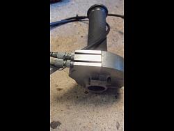
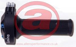
    You could junk the splitter completely if you used the 1970s TZ yamaha dual throttle control. The throttle action is smoother than you get with a splitter. Genuine ones will be hard to find at a reasonable price but new "clones" are available, but you easily have the skills to make one. If you become interested in making one I can take detailed internal photos.

    1974 XS/TX650 rebuild-dual-throttletz01.jpg Click for full size
    Original TZ Yamaha

    1974 XS/TX650 rebuild-dualthrottle01.jpg
    Modern clone.

  15. #270
    Supporting Member th62's Avatar
    Join Date
    Oct 2015
    Posts
    270
    Thanks
    0
    Thanked 503 Times in 168 Posts

    th62's Tools
    The 74 TX650 came with a dual cable throttle, nothing but a PITA, so I 'junked' it using a splitter I made for the BS38s. Post 149 here:

    1974 XS/TX650 rebuild

    This system was far, far superier to the dual throttle, easy to sync, neat and tidy and only one cable to worry about
    Last edited by th62; Mar 27, 2023 at 05:16 AM.

Thread Information

Users Browsing this Thread

There are currently 1 users browsing this thread. (0 members and 1 guests)

Bookmarks

Posting Permissions

  • You may not post new threads
  • You may not post replies
  • You may not post attachments
  • You may not edit your posts
  •